Watchdog Timer
M30240 Group
Rev.1.00 Sep 24, 2003 Page 37 of 360
The watchdog timer is initialized by writing to the watchdog timer start register (address 000E
16
) and
when a watchdog timer interrupt request is generated. The prescaler is initialized only when the
microcomputer is reset. After a reset, the watchdog timer and prescaler are both stopped. The count is
started by writing to the watchdog timer start register (address 000E
16
).
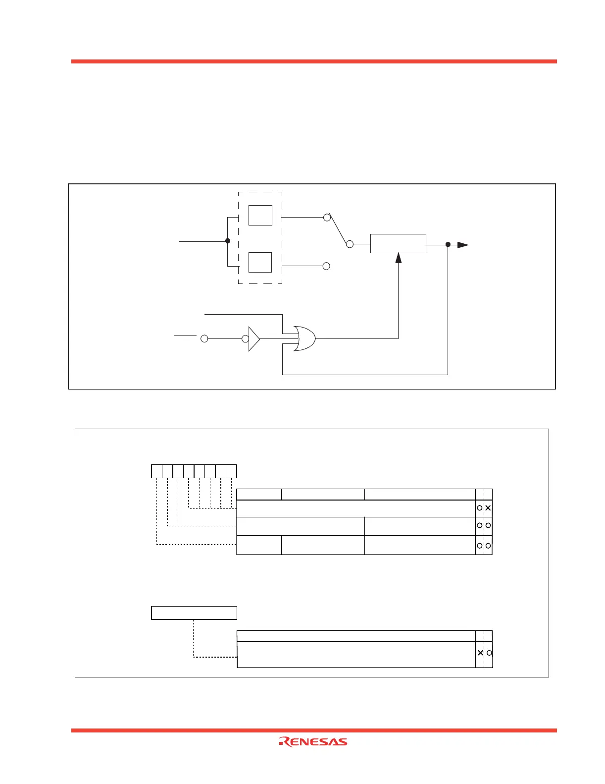
Figure 1.21 shows the block diagram of the watchdog timer. Figure 1.22 shows the watchdog timer-
related registers.
Figure 1.21: Block diagram of watchdog timer
Figure 1.22: Watchdog timer control and start registers
1/16
1/128
Watchdog timer
Set to 7FFF
16
WDC7 = 0
WDC7 = 1
RESET
Write to the watchdog
timer start register
(address 000E
16
)
Internal clock
Φ
Prescaler
Watchdog timer
interrupt request
Watchdog timer control register (Note)
Symbol Address When reset
WDC 000F
16 000XXXXX2
FunctionBit symbol WR
b7 b6 b5 b4 b3 b2 b1 b0
High-order bit of Watchdog timer
WDC7
Bit name
Prescaler select bit
0
:
Divided by 16
1 : Divided by 128
Watchdog timer start register
Symbol Address When reset
WDTS 000E
16 Indeterminate
WR
b7 b0
Function
Reserved bit
Must always be set to “0”
00
Note: Set the desired prescale value before initializing the Watchdog timer.
The Watchdog timer is initialized and starts counting after the first write instruction
to this register after reset. Writing any value to this register resets the counter to
7FFF
16.
 Loading...


