RL78/F13, F14 CHAPTER 8 TIMER RD
R01UH0368EJ0210 Rev.2.10 626
Dec 10, 2015
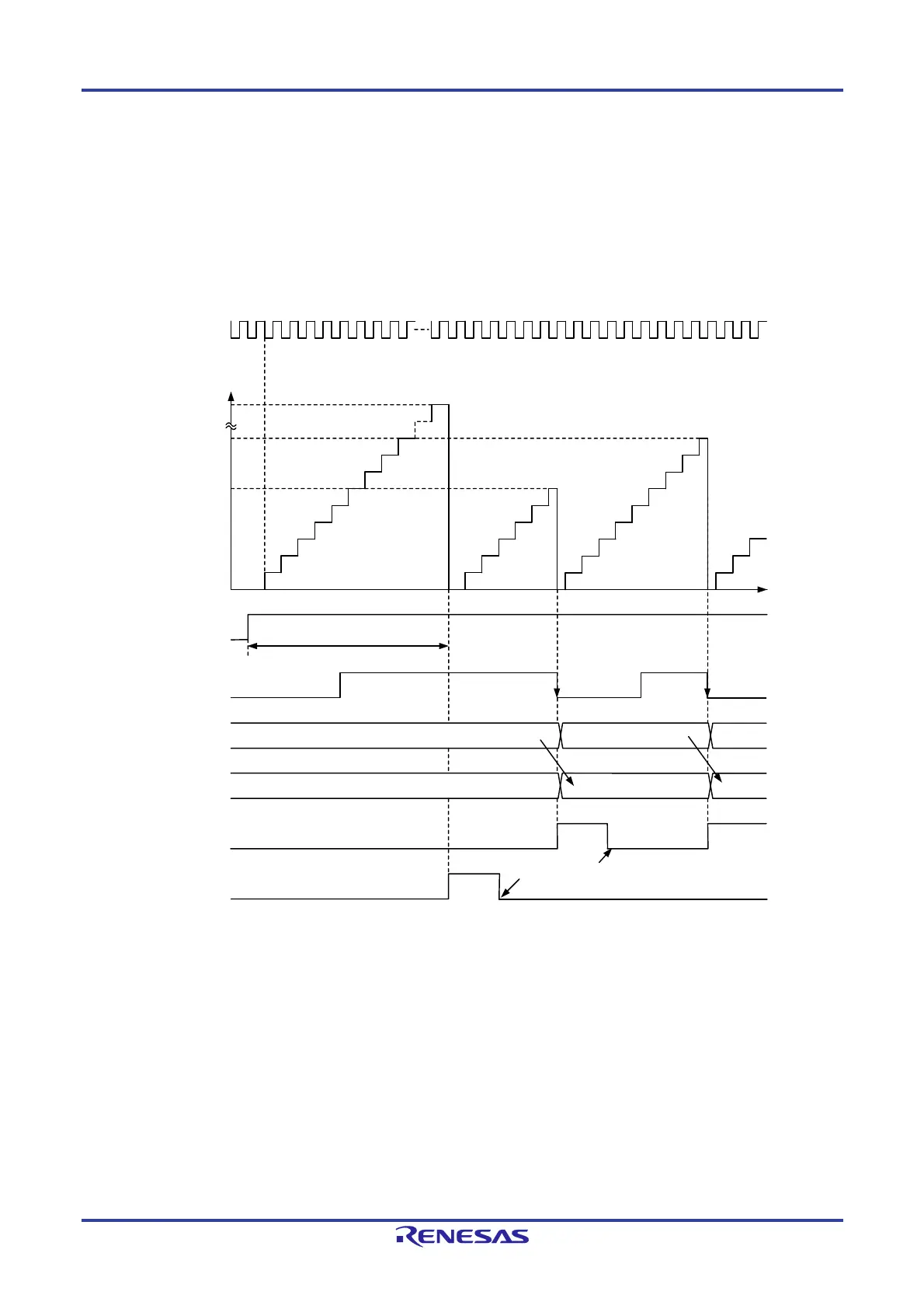
(1) Operation Example
By setting bits CCLR0 to CCLR2 in the TRDCRi register (i = 0 or 1), the timer RDi counter value is reset by an input
capture/compare match. Figure 8-46 shows an operation example with bits CCLR2 to CCLR0 set to 001B.
If the input capture operation has been set to clear the count during operation and is performed when the timer count
value is FFFFH, depending on the timing between the count source and input capture operation interrupt flags bits
IMFA to IMFD and OVF in the TRDSRi register may be set to 1 simultaneously.
Figure 8-46. Operation Example of Input Capture Function
FFFFH
0009H
0006H
65536
0000H
Transfer
0009H0006H
0006H
Transfer
Time
TRDCLK input
count source
Count value
in TRDi register
TSTARTi bit in
TRDSTR register
TRDIOAi input
TRDGRAi register
TRDGRCi register
IMFA bit in
TRDSRi register
OVF bit in
TRDSRi register
Remark
i = 0 or 1
The above diagram applies under the following conditions:
Bits CCLR2 to CCLR0 in the TRDCRi register are set to 001B (TRDi register is set to 0000H by TRDGRAi register input capture).
Bits TCK2 to TCK0 in the TRDCRi register are set to 101B (TRDCLK input for the count source).
Bits CKEG1 and CKEG0 in the TRDCRi register are set to 01B (count at the falling edge for the count source).
Bits IOA2 to IOA0 in the TRDIORAi register are set to 101B (input capture at the falling edge of TRDIOAi input).
The TRDBFCi bit in the TRDMR register is set to 1 (TRDGRCi register is buffer register for TRDGRAi register).
Set to 0 by a program
 Loading...


