Technical Bulletin PAGE: 4/7
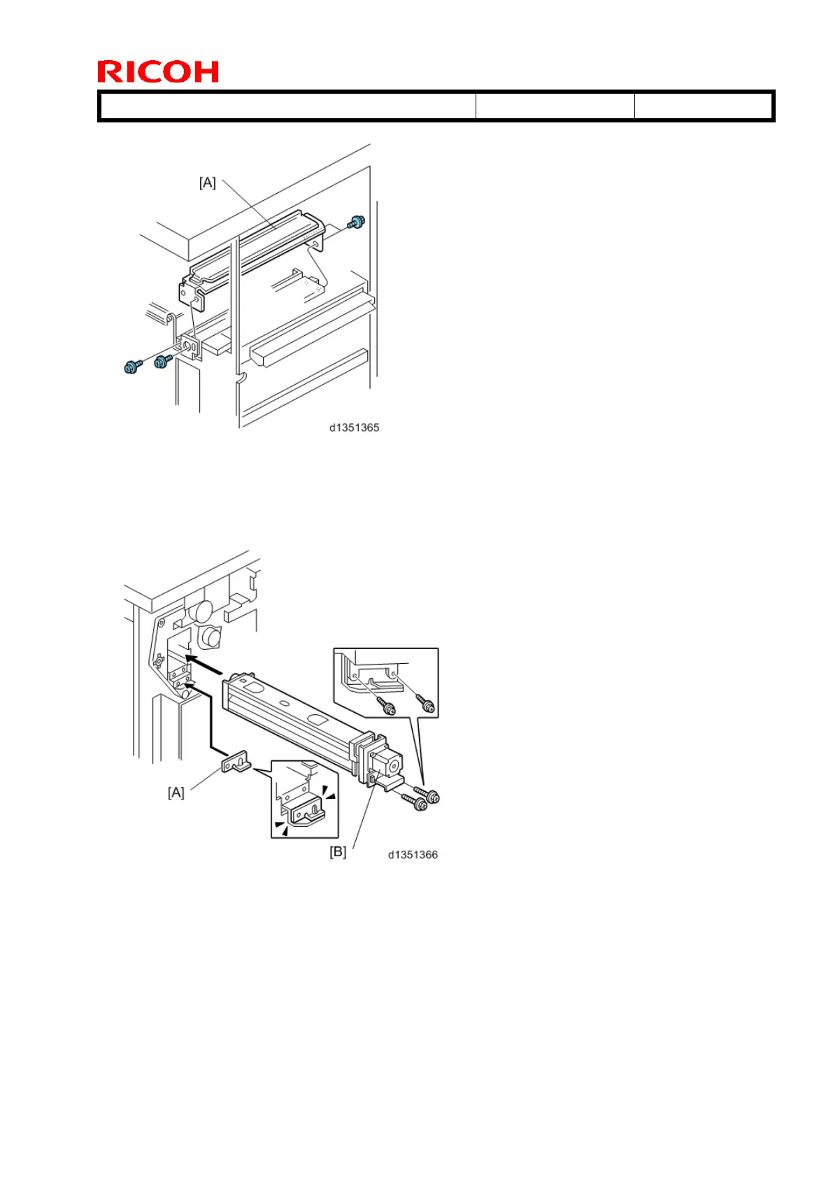
12. Remove the paper guide [A] (4 screws).
13. Position the 2 mm spacer [A] and attach the punch unit [B] (2 screws, M3 x 10).
14. Use one of the screws removed from the motor protector plate to fasten the remaining
two spacers to the frame as shown.
NOTE:
These extra spacers can be used to adjust the position of the punch holes (front to rear,
across the page).
 Loading...