336 Rockwell Automation Publication 2080-UM002M-EN-E - April 2022
Appendix G Connect to Networks using DF1
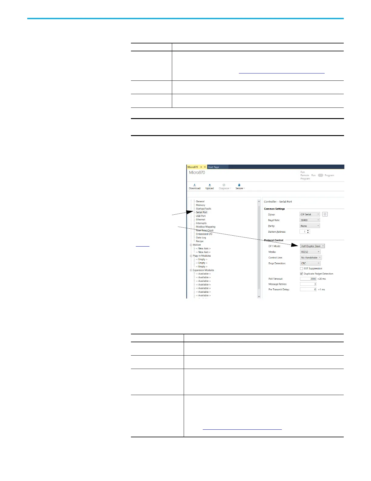
Configure a Slave Station To choose the controller as a slave station, follow the steps below using your
programming software:
Define these parameters when configuring a Micro800 controller as a slave
station.
RTS Send Delay
Defines the amount of time, in 20 millisecond increments, that elapses between the
assertion of the RTS signal and the beginning of the message transmission. This time allows
the modem to prepare to transmit the message. The Clear-to-Send (CTS) signal must be
high for transmission to occur. See RTS Send Delay and RTS Off Delay on page 330 for
further guidelines for setting this parameter.
Pre-Transmit Delay
Defines the amount of time, in 1 millisecond increments, that elapses between when the
controller has a message to send and when it asserts the RTS signal.
Message Retries
Defines the number of times a master station retries a message before it declares the
message undeliverable.
IMPORTANT The unconnected timeout value in the Message instruction should
always be larger than the pre-transmit delay.
Table 78 - Configure a Micro800 Controller as a Master Using Message-based
Communication Mode (Continued)
Parameter Selections
1. To bring up the configuration page, click
Serial Port.
2. On the Serial Port configuration page, select
Half-Duplex Slave for your DF1 Mode.
3. Configure the rest of the communication
driver according to Table 79
.
Table 79 - Configure a Micro800 Controller as a Slave Station
Parameter Selections
Baud Rate
Select a communication rate that all devices in your system support. Configure all
devices in the system for the same communication rate.
Parity
Parity provides additional message packet error detection. To implement even parity
checking, choose Even. To implement no parity checking, choose None.
Node Address
A node address identifies the controller on the DF1 half-duplex link. Each station on a
link must have a unique node address. Choose an address between 0
10
and 254
10.
Node address 255
10
is the broadcast address, which you cannot select as a station’s
individual address.
Control Line
This parameter defines the mode in which the driver operates. Choose a method
appropriate for your system’s configuration:
• If you are not using a modem, choose NO HANDSHAKE.
• If the master modem is full duplex and the slave modem is half-duplex, choose
HALF-DUPLEX WITHOUT CONTINUOUS CARRIER (RTS/CTS).
See page Modem Control Line Operation
on page 328 for descriptions of the control
line operation settings.

 Loading...


