340 Rockwell Automation Publication 2080-UM002M-EN-E - April 2022
Appendix G Connect to Networks using DF1
Configure the Store and Forward Table
The Store and Forward function in Micro800 controllers provide two methods
to configure – Dynamic, which requires creating a Store & Forward table, or
Static, which you can directly configure in Connected Components
Workbench software.
Use the static method when you want to configure the Store and Forward
tables while the controller is offline. Use the dynamic method when you want
to configure the Store and Forward tables while the controller is in RUN mode.
The dynamic Store and Forward table occupies a BOOL array [0…255] or
DWORD array [0…7] data type. Each bit in this array corresponds to a DF1
Radio Modem node address.
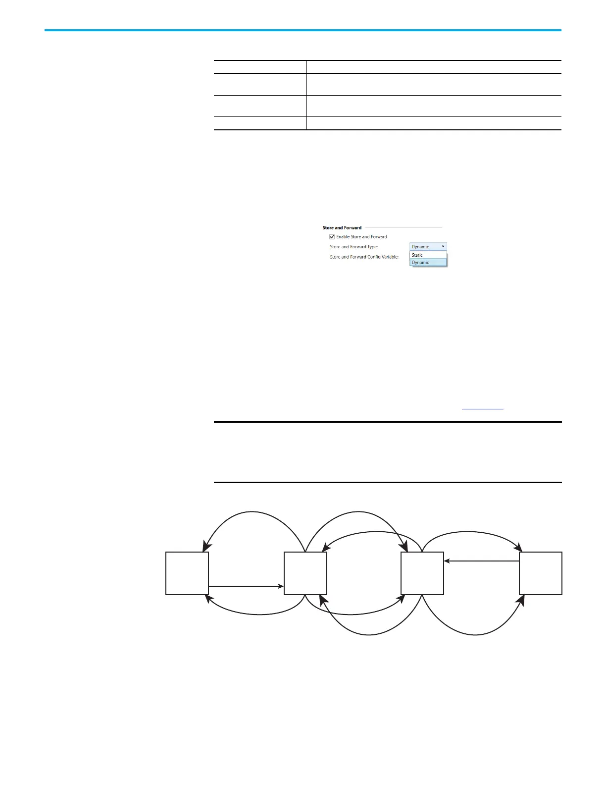
In order to configure a Micro800 controller to Store and Forward message
packets between two other nodes, the bits corresponding to the addresses of
those two other nodes must be set. For instance, if node 2 is used to Store and
Forward message packets between nodes 1 and 3, then both Bit 1 and Bit 3
would have to be set in the Store and Forward table (see Figure 30
).
Figure 30 - Applying Store and Forward with DF1 Radio Modem Protocol
Undelivered Packets
The number of messages that were sent by the controller but not acknowledged by
the destination device.
Duplicate Received
The number of times the controller received a message packet identical to the
previous message packet.
Bad Characters Received The number of data characters received with transmission errors by the controller.
IMPORTANT Once Store and Forward is enabled, duplicate packet detection is also
automatically enabled. Whenever Store and Forward is used within a
radio modem network, every node should have Store and Forward
enabled, even if all of the bits in the file are cleared, so that duplicate
packets will be ignored.
Table 82 - DF1 Radio Modem Communication Diagnostics Parameters (Continued)
Status Field Definition
Node 4
No Bits
Node 3
1, 2, 4
Node 2
1, 3, 4
Node 1
No Bits
CMD 1
(DST = 4, SRC = 1)
REPLY 1
(DST = 1, SRC = 4)
CMD1
(1st Rebroadcast)
Note 1
(2nd Rebroadcast)
REPLY 1
CMD 1
(2nd Rebroadcast)
(1st Rebroadcast)
REPLY 1
Note 4
Note 2
Note 1 – The link layer of Node 1 blocks the re-transmission of a packet that is received with the SRC byte equal to the receiving node’s station
address. Packets received that originate from the receiving node should never be re-transmitted.
Note 2 – To prevent Node 2 from re-transmitting a duplicate packet, the link layer of Node 2 updates the duplicate packet table with the last 20
packets received.
Note 3 – The link layer of Node 4 blocks the re-transmission of a packet that is received with the SRC byte equal to the receiving node’s station
address. Packets received that originate from the receiving node should never be re-transmitted.
Note 4 – To prevent Node 3 from re-transmitting a duplicate packet, the link layer of Node 3 updates the duplicate packet table with the last 20
packets received.
Note 3

 Loading...


