196 Rockwell Automation Publication 2080-UM002M-EN-E - April 2022
Chapter 9 Use the High-Speed Counter and Programmable Limit Switch
The bits in the gray boxes are unused. For the 10-point controller, the first 4
bits of the mask word are used and the remaining mask bits are not functional
because they do not correlate to any physical outputs on the base unit. For the
16, 24 and 48-point controllers, the first 6, 10 and 20 bits of the mask word are
used, respectively.
The mask bit pattern can be configured only during initial setup.
The High Preset Output defines the state (1 = ON or 0 = OFF) of the outputs on
the controller when the high preset is reached. For more information on how
to directly turn outputs on or off based on the high preset being reached, see
Output Mask Bits (HSCAPP.OutputMask)
on page 195.
The high output bit pattern can be configured during initial setup, or while the
controller is operating. Use the HSC function block to load the new parameters
while the controller is operating.
The Low Preset Output defines the state (1 = “on”, 0 = “off”) of the outputs on
the controller when the low preset is reached. See Output Mask Bits
(HSCAPP.OutputMask) on page 195 for more information on how to directly
turn outputs on or off based on the low preset being reached.
The low output bit pattern can be configured during initial setup, or while the
controller is operating. Use the HSC function block to load the new parameters
while the controller is operating.
HSC STS (HSC Status) Data
Structure
Define an HSC STS data (HSC status information data, data type HSCSTS)
when programming an HSC.
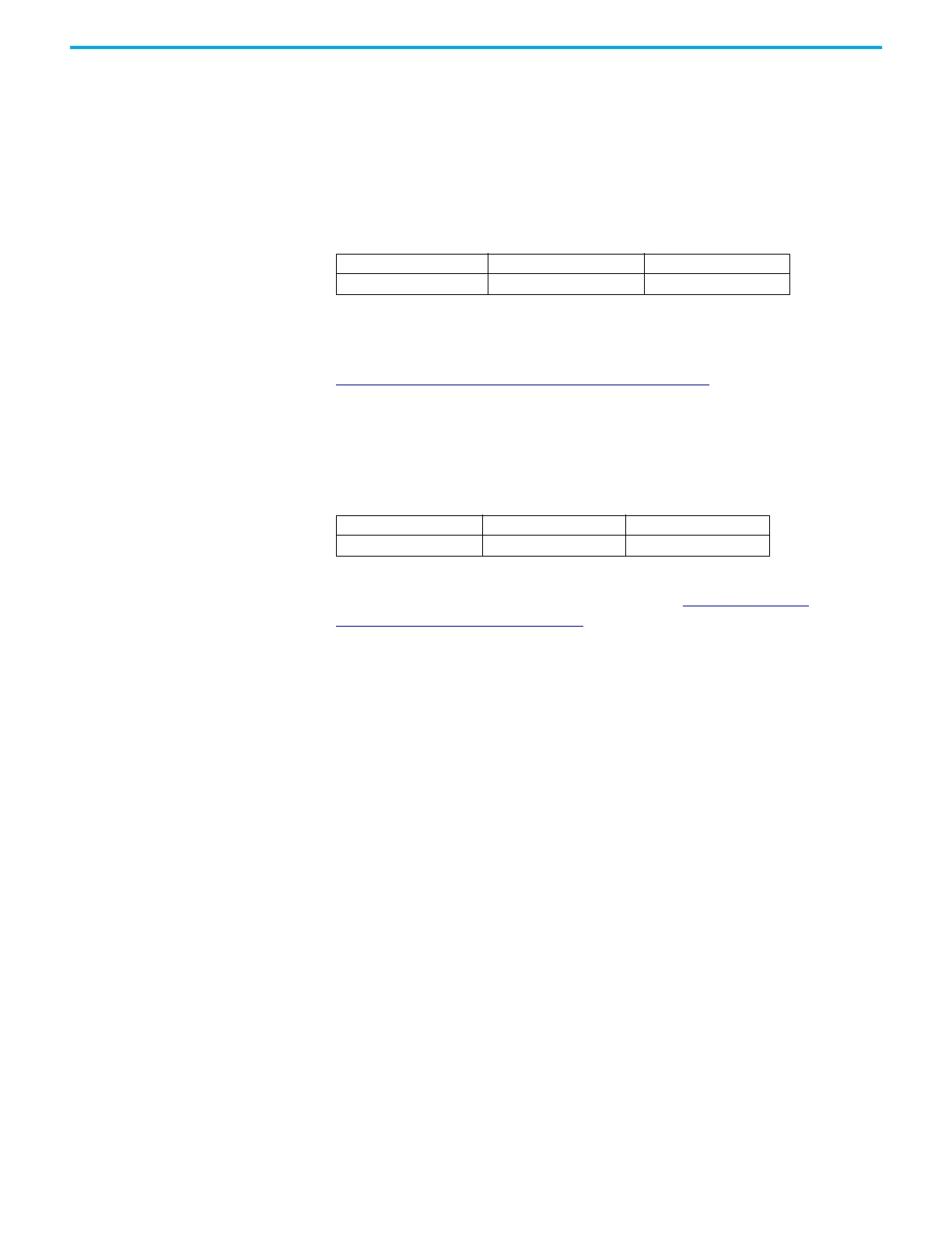
High Preset Output (HSCAPP.HPOutput)
Description Data Format User Program Access
HSCAPP.HPOutput long word (32 bit binary) read/write
Low Preset Output (HSCAPP.LPOutput)
Description Data Format User Program Access
HSCAPP.LPOutput long word (32 bit binary) read/write

 Loading...


