Rockwell Automation Publication 2080-UM002M-EN-E - April 2022 141
Chapter 8 Motion Control
To use the Micro800 motion feature, you need to:
1. Configure the Axis Properties
See Motion Axis Configuration in Connected Components Workbench
on page 163 for instructions.
2. Write your motion program through the Connected Components
Workbench software
For instructions on how to use the Micro800 motion control feature, see
the quickstart instructions, Use the Motion Control Feature on Micro800
Controllers, publication 2080-QS001
.
3. Wire the Controller
For fixed and configurable inputs/outputs, see Input and Output Signals
on page 141. See Sample Motion Wiring Configuration on 2080-LC30-
xxQVB / 2080-LC50-xxQVB / 2080-LC70-xxQVB on page 143 for
reference.
The next sections provide a more detailed description of the motion
components. You can also see the Connected Components Workbench Online
Help for more information about each motion function block and their
variable inputs and outputs.
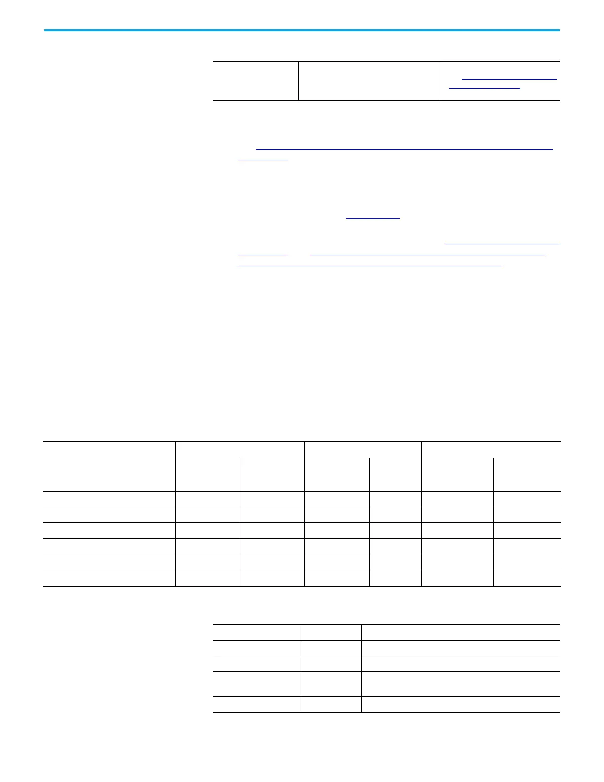
Input and Output Signals Multiple input/output control signals are required for each motion axis, as
described in the next tables. PTO Pulse and PTO Direction are required for an
axis. The rest of the input/outputs can be disabled and reused as regular I/O.
Jerk
Rate of change of acceleration. The Jerk
component is mainly of interest at the start
and end of motion. Too high of a Jerk may
induce vibrations.
• See Acceleration, Deceleration, and
Jerk Inputs on page 145.
Components of Motion Control (Continued)
Fixed PTO Input/Output
Motion Signals PTO0 (EM_00) PTO1 (EM_01) PTO2 (EM_02)
Logical Name in
Software
Name on
Terminal Block
Logical Name in
Software
Name on
Terminal
Block
Logical Name in
Software
Name on Terminal
Block
PTO pulse _IO_EM_DO_00 O-00 _IO_EM_DO_01 O-01 IO_EM_DO_02 O-02
PTO direction _IO_EM_DO_03 O-03 _IO_EM_DO_04 O-04 IO_EM_DO_05 O-05
Lower (Negative) Limit switch _IO_EM_DI_00 I-00 _IO_EM_DI_04 I-04 IO_EM_DI_08 I-08
Upper (Positive) Limit switch _IO_EM_DI_01 I-01 _IO_EM_DI_05 I-05 IO_EM_DI_09 I-09
Absolute Home switch _IO_EM_DI_02 I-02 _IO_EM_DI_06 I-06 IO_EM_DI_10 I-10
Touch Probe Input switch _IO_EM_DI_03 I-03 _IO_EM_DI_07 I-07 IO_EM_DI_11 I-11
Configurable Input/Output
Motion Signals Input/Output Notes
Servo/Drive On OUTPUT Can be configured as any embedded output.
Servo/Drive Ready INPUT Can be configured as any embedded input.
In-Position signal (from
servo/motor)
INPUT Can be configured as any embedded input.
Home Marker INPUT Can be configured as any embedded input, from input 0...15.

 Loading...


