Rockwell Automation Publication 2080-UM002M-EN-E - April 2022 339
Appendix G Connect to Networks using DF1
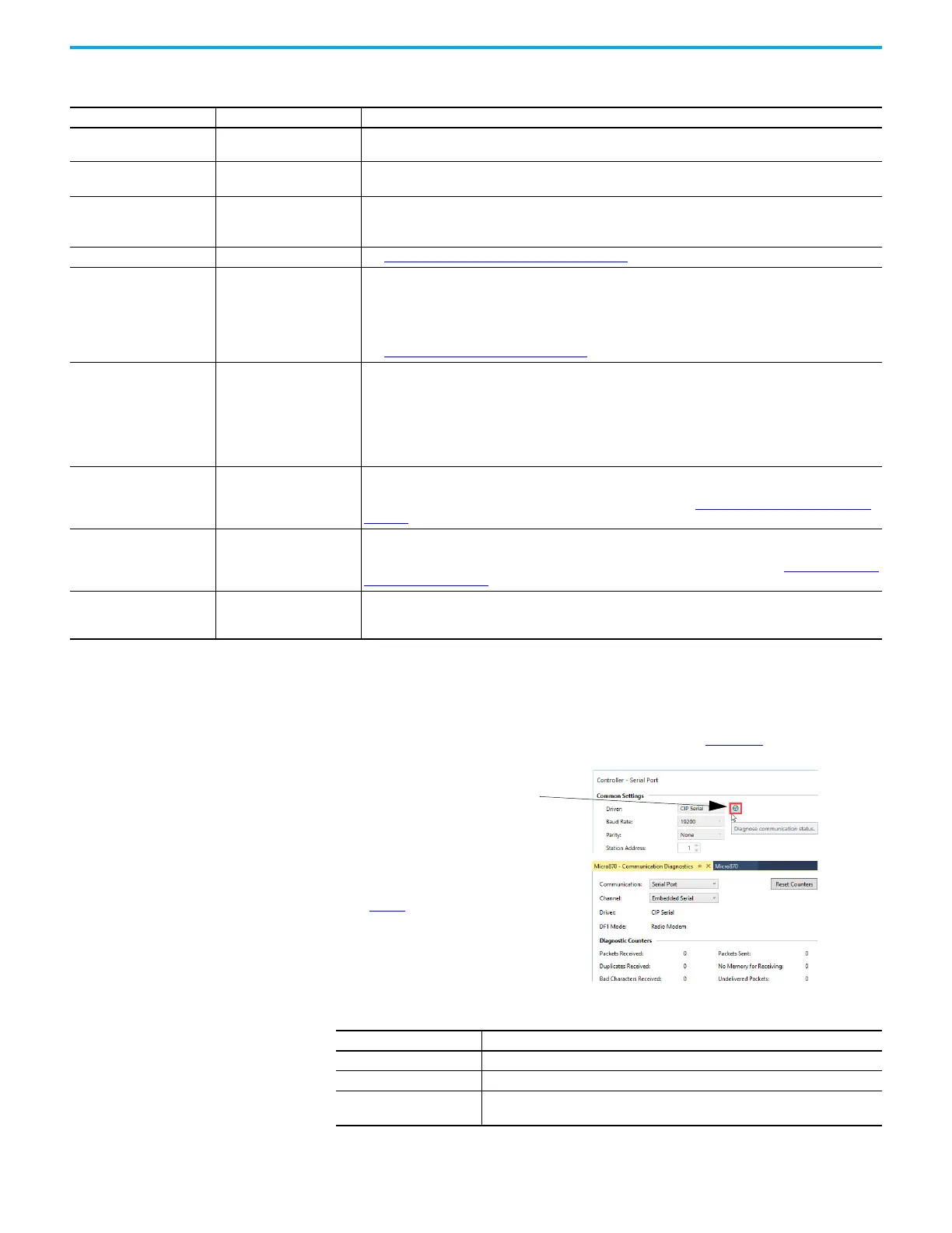
DF1 Radio Modem Communication Diagnostics
Communication diagnostics is available while connected to the controller by
clicking the Diagnose communication status button. Table 82 explains
information regarding the diagnostic counter data displayed.
Table 81 - Configure a Micro800 controller for DF1 Radio Modem communication
Parameter Default Selections
Baud Rate 19,200
Select a communication rate that all devices in your system support. Configure all devices in the system for
the same communication rate.
Parity None
Parity provides additional message packet error detection. To implement even parity checking, choose Even.
To implement odd parity checking, choose Odd. To implement no parity checking, choose None.
Node Address 1
A node address identifies the controller on the DF1 half-duplex link. Each station on a link must have a unique
node address. Choose an address between 0
10
and 254
10.
Node address 255
10
is the broadcast address, which
you cannot select as a station’s individual address.
Enable Store and Forward Not selected (Disabled) See Configure the Store and Forward Table
on page 340 for more information.
Control Line No Handshake
This parameter defines the mode in which the driver operates. Choose a method appropriate for your
system’s configuration:
• If you are not using a modem, choose NO HANDSHAKE.
• Half-Duplex without Continuous Carrier (RTS/CTS)
• Half-Duplex with DCD Handshaking
See Modem Control Line Operation
on page 328 for descriptions of the control line operation settings.
Error Detection CRC
With this selection, you choose the how the controller checks the accuracy of each DF1 packet transmission.
BCC: This algorithm provides a medium level of data security. It cannot detect:
– transposition of bytes during transmission of a packet
– the insertion or deletion of data values of zero within a packet
CRC: This algorithm provides a higher level of data security.
Select an error detection method that all devices in your configuration can use.
When possible, choose CRC.
RTS Off Delay 0
Defines the amount of time, in 20 millisecond increments, that elapses between the end of the message
transmission and the de-assertion of the RTS signal. This time delay is a buffer to make sure that the modem
has transmitted the message, but should normally be left at zero. See RTS Send Delay and RTS Off Delay
on
page 330 for further guidelines for setting this parameter.
RTS On Delay 0
Defines the amount of time, in 20 millisecond increments, that elapses between the assertion of the RTS
signal and the beginning of the message transmission. This time allows the modem to prepare to transmit
the message. The Clear-to-Send (CTS) signal must be high for transmission to occur. See RTS Send Delay and
RTS Off Delay on page 330 for further guidelines for setting this parameter.
Pre-Transmit Delay 0
Defines the amount of time, in 1 millisecond increments, that elapses between when the controller has a
message to send and when it asserts the RTS signal (if handshaking is selected) or begins transmitting (if no
handshaking is selected).
Table 82 - DF1 Radio Modem Communication Diagnostics Parameters
Status Field Definition
Packets Sent The total number of DF1 messages sent by the controller.
Packets Received The number of messages received with no errors.
No Memory for Receiving
The number of times the controller could not receive a message because it did not
have available memory.
1. Click Diagnose communication status to bring
up the DF1 Radio Modem diagnostics.
2. See Table 82 for details concerning the DF1
Radio Modem Communication Diagnostics
screen.

 Loading...


