36 Rockwell Automation Publication 2080-UM002M-EN-E - April 2022
Chapter 2 About Your Controller
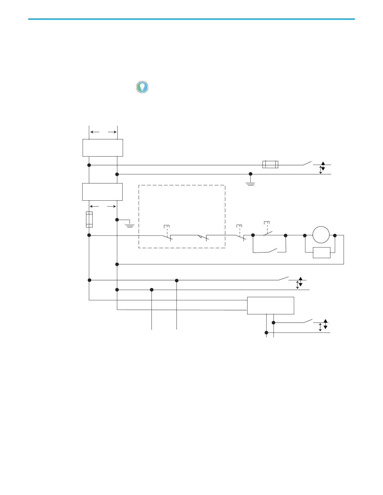
• In the following illustration, input and output circuits are shown with
MCR protection. However, in most applications, only output circuits
require MCR protection.
The following illustrations show the Master Control Relay wired in a grounded
system.
Figure 1 - Schematic – Using IEC Symbols
In most applications input circuits do not require MCR protection; however, if
you need to remove power from all field devices, you must include MCR
contacts in series with input power wiring.
Disconnect
Isolation
transformer
Emergency-stop
push button
Fuse
MCR
230V AC
I/O circuits
Operation of either of these contacts will remove
power from the external I/O circuits, stopping
machine motion.
Fuse
Overtravel limit
switch
MCR
MCR
MCR
Stop Start
Line terminals: Connect to terminals of power supply.
115V AC or 230V AC
I/O circuits
L1
L2
230V AC
Master Control Relay (MCR)
Cat. No. 700-PK400A1
Suppressor
Cat. No. 700-N24
MCR
Suppr.
24V DC
I/O circuits
(Lo)
(Hi)
DC power supply.
Use IEC 950/EN 60950
X1 X2
115V AC
or 230V AC
Line terminals: Connect to 24V DC terminals of power supply.
_
+

 Loading...


