Troubleshooting
10-3
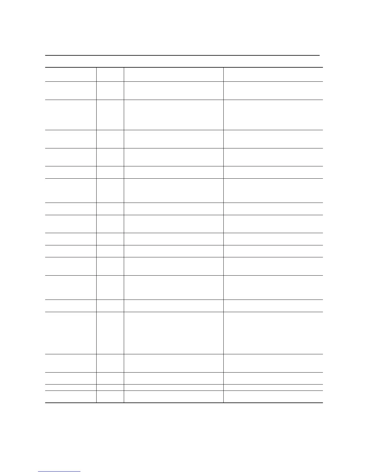
Table 10.A SMC Fault Display Explanation
①
Prestart fault indication.
②
To further define this fault, the user can clear the fault and re-initiate a start signal. If the fault condition is still present, the controller will display either a Power Loss
or a Line Fault with the phase indicated.
Display
Fault
Code
Possible Causes Possible Solutions
Power Loss
①
(with phase indication)
F1, F2, F3,
F30, F31,
& F32
• Missing supply phase (as indicated)
• Converter module and/or cable failure
• Check for open line (i.e., blown line fuse)
• Inspect converter module cable connections
Line Fault
①
(with phase indication)
F11, F12,
F13, F26,
F27, & F28
• Missing supply phase
• Motor not connected properly
•Shorted SCR
• Converter module and/or cable failure
• Check for open line (i.e., blown fuse)
• Check for open load lead
• Check for shorted SCR; replace if necessary
• Inspect converter module cable connections
• Consult the factory
Line Fault
②
(no phase indication)
F15 and
F29
• Missing supply phase
• Motor not connected properly
•Shorted SCR
• Check for open line ( i.e., blown fuse)
• Check for open load lead
• Check for shorted SCR; replace if necessary
Voltage Unbalance F10
• Supply unbalance is greater than the user-
programmed value
• The delay time is too short for the application
• Check power system and correct if necessary
• Extend the delay time to match the
application requirements
Phase Reversal F16
• Incoming supply voltage is not in the
expected ABC sequence
• Check power wiring
Undervolt F4
• Supply voltage is less than user-programmed
value
• The delay time is too short for the application
• Check power system and correct if necessary
• Correct the user-programmed value
• Extend the delay time to match the
application requirements
Overvolt F5
• Supply voltage is greater than user-
programmed value
• Check power system and correct if necessary
• Correct the user-programmed value
Overload F7
• Motor overloaded
• Overload parameters are not matched to the
motor
• Check motor overload condition
• Check programmed values for overload class
and motor FLC
Stall F6
• Motor has not reached full speed by the end
of the programmed ramp time
• Correct source of stall
Jam F19
• Motor current has exceeded the user
programmed jam level.
• Correct source of jam
Underload F9
• Broken motor shaft
• Broken belts, toolbits, etc.
• Pump cavitation
• Repair or replace motor
• Check machine
•Check pump system
Open Gate
(with phase indication)
F23-F25
• Open gate circuitry
• Loose gate lead (180–1000A)
• Perform resistance check; replace power
module if necessary
• Check gate lead connections to the interface
board
Excess Starts/Hr. F64
• Number of starts in a one hour period has
exceeded the value programmed
• Wait an appropriate amount of time to restart
• Turn off the Starts/Hr. feature
Controller Temperature F8
• Controller ventilation blocked
• Controller duty cycle exceeded
• Fan failure (if used)
• Ambient temperature limit exceeded
• Failed thermistor
• Failed control module
• Check for proper ventilation
• Check application duty cycle
•Replace fan
• Wait for controller to cool or provide external
cooling
• Replace power module
• Replace control module
Comm Fault F21
• Communication disconnection at the serial
port
• Check for a communication cable
disconnection to the SMC Dialog Plus
controller
System Faults
F128 &
above
• Internal control module hardware failure • Replace control module
MPU Comm Fault — • Internal control module hardware failure • Replace control module
Curr Fdbk Loss F20
• Converter module cable disconnection • Inspect converter module cable and
connections

 Loading...


