Serial Communications
8-19
1203-GD1 Communication Module Switch Settings
The following information is provided to explain the required 1203-
GD1 communication module switch settings for this example. Refer
to the 1203-GD1 manuals for further details related to the switch
settings.
Example Information
①
This configuration requires a 1/4 rack size allocation.
②
The SMC Dialog Plus controller does not support Datalinks.
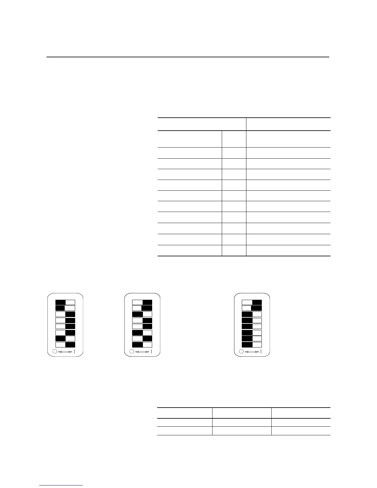
Switch Settings
I/O Addressing
The 1203-GD1 communication module uses 1-slot addressing. Based
on the module switch settings as described above, the discrete I/O can
be mapped to the PLC I/O Image as shown below.
Description Switch Setting
SMC Rack Address: 02
SW1: Switches 1 & 2 (Not Used),
Switches 3-6 & 8 (On), Switch 7 (Off)
Starting Group Address: 0 SW2: Switches 1 & 2 (On)
Last Rack: No SW2: Switch 3 (Off)
Hold Last State: Yes SW2: Switch 4 (On)
Fault on Comm Loss: Yes SW2: Switch 5 (On)
Fault Controller: No SW2: Switch 6 (Off)
R I/O Baud Rate: 115k SW2: Switch 7 (On), Switch 8 (Off)
Block Transfer:
Yes
①
SW3: Switch 1 (On)
Logic Cmd/Status:
Yes
①
SW3: Switch 2 (On)
Reference/Feedback:
No
①
SW3: Switch 3 (Off)
Datalinks:
No
①
②
SW3: Switch 4-8 (Off)
SW1
8 7 6 5 4 3 2 1
Not Used
Not Used
On
On
On
On
Off
On
SW2
8 7 6 5 4 3 2 1
Starting Module Group (0)
Starting Module Group (0)
Last Rack Setting (Off)
Hold Last State (On)
Fault on Comm Loss (On)
Fault Controller (Off)
R I/O Baud Rate (115k)
R I/O Baud Rate (115k)
SW3
8 7 6 5 4 3 2 1
Block Transfer On
Logic Cmd/Sts On
Reference/Fdbk Off
Datalink A Off
Datalink B Off
Datalink C Off
Datalink D Off
Truncate Last Datalink Off
PLC I/O Group Number Output Image Input Image
0 Block Transfer Block Transfer
1 Logic Command Logic Status

 Loading...


