8-20
Serial Communications
Remote I/O Examples (cont.)
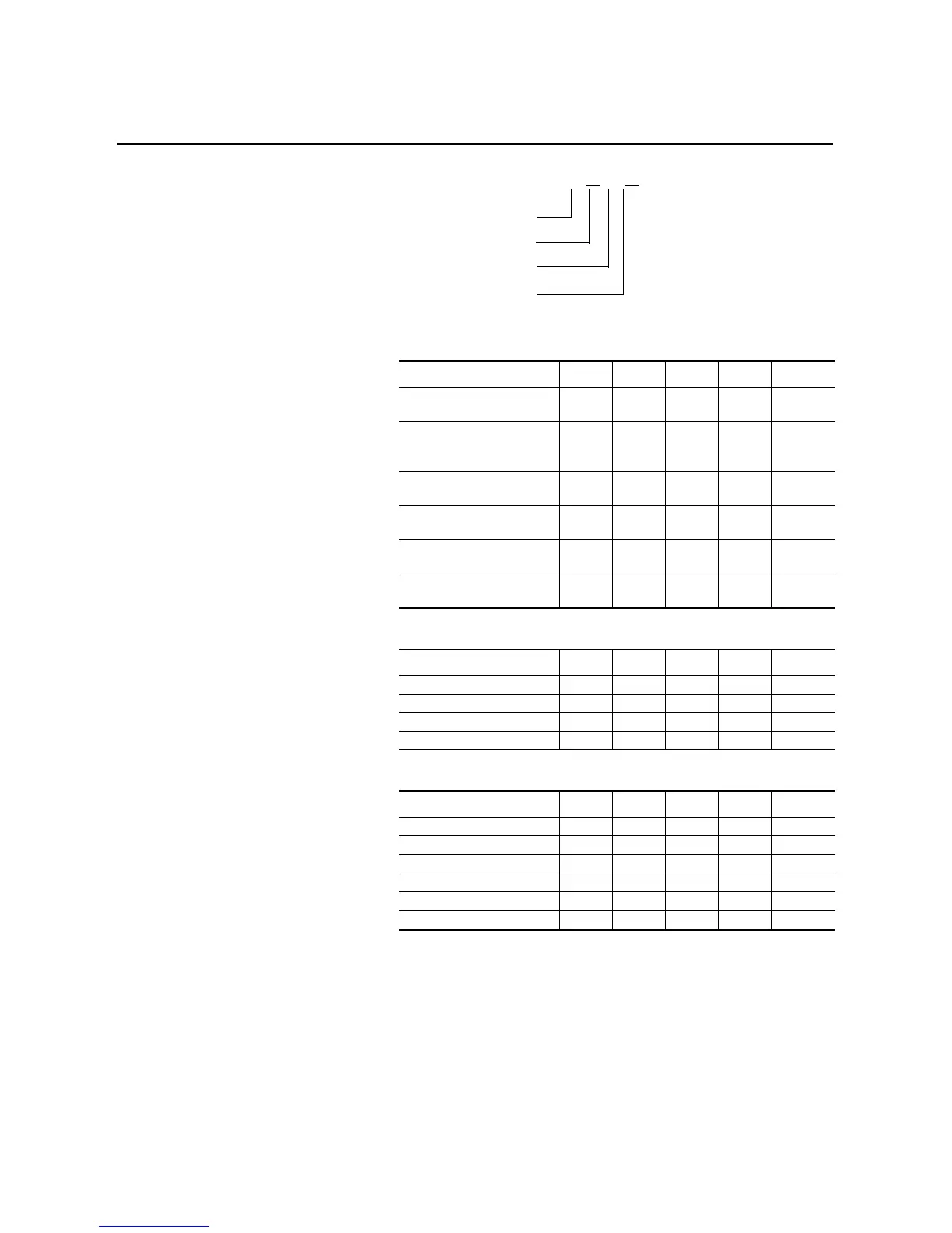
Addressing Format
Communication Module Block Transfer Status Word Addresses
①
SMC Dialog Plus Controller Logic Control Addresses
①
SMC Dialog Plus Controller Status Addresses
①
①
The addresses shown are example-specific. Addresses for any given installation can be determined,
based upon the 1203-GD1 communication module switch settings for: rack address, starting group
number, block transfer, logic command/status, and reference/feedback by applying the I/O
addressing format for PLC-5 controllers.
②
Refer to Figure 3.1 of the Bulletin 1203 Remote I/O Communication Module.
③
Refer to Table 8.A.
④
Refer to Table 8.B.
⑤
This is the octal address representation for this bit.
Bit Description I or O Rack Group
Bit
②
Address
Block Transfer Ready
(BT_READY)
I 02 0 10 I:020/10
Block Transfer Write in
Progress
(BTW_IN_PROG)
I 02 0 11 I:020/11
Block Transfer Read Available
(BTR_AVAIL)
I 02 0 12 I:020/12
Block Transfer Wait
(BT_WAIT)
I 02 0 13 I:020/13
Block Transfer Error
(BT_ERROR)
I 02 0 14 I:020/14
Block Transfer Write Available
(BTW_AVAIL)
I 02 0 15 I:020/15
Bit Description I or O Rack Group
Bit
③
Address
Stop O 02 1 00 O:021/00
Start O 02 1 01 O:021/01
Option Command O 02 1 02 O:021/02
Clear Fault O 02 1 03 O:021/03
Bit Description I or O Rack Group
Bit
④
Address
Enabled I 02 1 00 I:021/00
Running I 02 1 01 I:021/01
Starting I 02 1 04 I:021/04
Stopping I 02 1 05 I:021/05
Fault I 02 1 07 I:021/07
At Speed I 02 1
10
⑤
I:021/10
I
for input or
O
for output
2-digit I/O rack number
I/O group number (0–7)
Input or output number
(octal bit address: 0–7, 10–17)
I : 02
0/12

 Loading...


