Serial Communications
8-25
Example Information
①
The SMC Dialog Plus controller does not support Datalinks.
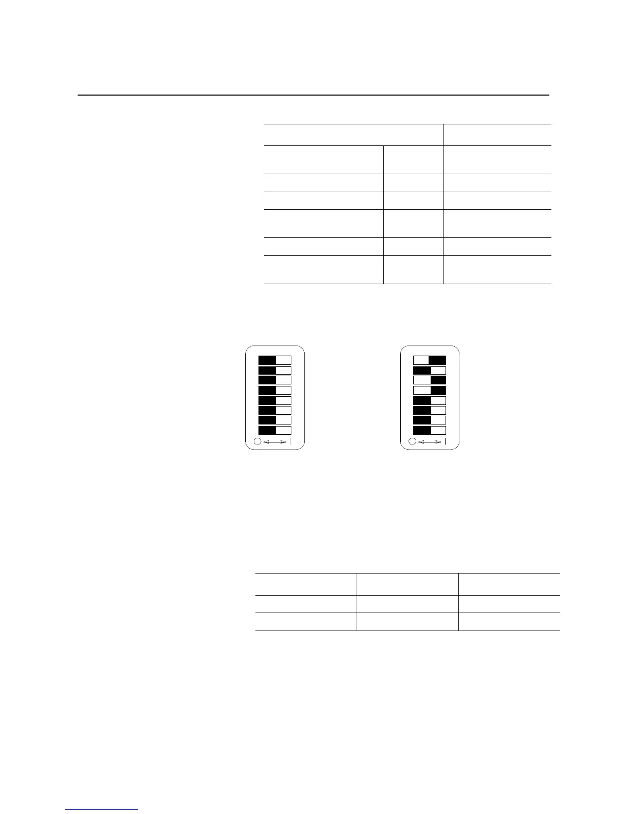
Switch Settings
I/O Mapping
The SMC Dialog Plus controller’s first two words of data are pre-
configured in the 1203-GK5 communication module as follows:
①
The SMC Dialog Plus controller does not utilize this feature; a value of zero should be given.
②
The feedback word is the value of parameter 4, Current Phase A.
Description Switch Setting
Node Address: 13 SW2, Switches 1, 3 & 4 (On)
Switches 2, 5 & 6 (Off)
Data Rate: 125k SW2, Switches 7 & 8 (Off)
Datalinks: No
①
SW1, Switches 1 - 4 (Off)
Zero data to logic command on
fault:
Yes SW1, Switch 6 (Off)
Fault on comm loss: Yes SW1, Switch 7 (Off)
Fault on PLC/SLC program/idle
modes:
Yes SW1, Switch 8 (Off)
Disabled Datalink A (Off)
Disabled Datalink B (Off)
Disabled Datalink C (Off)
Disabled Datalink D (Off)
Not Used (Off)
Zero Data (Off)
Fault on Comm Loss (Off)
Fault on Program/Idle (Off)
SW1
SW2
8
8
7
7
6
6
5
5
4
4
3
3
2
2
1
1
Node Address 13 (On)
Node Address 13 (Off)
Node Address 13 (On)
Node Address 13 (On)
Node Address 13 (Off)
Node Address 13 (Off)
Data Rate = 125k (Off)
Data Rate = 125k (Off)
Word Output Data Input Data
1 Logic Command Logic Status
2
Reference
①
Feedback
②

 Loading...


