3-8
Wiring
Standard Controller
Wiring Diagrams (cont.)
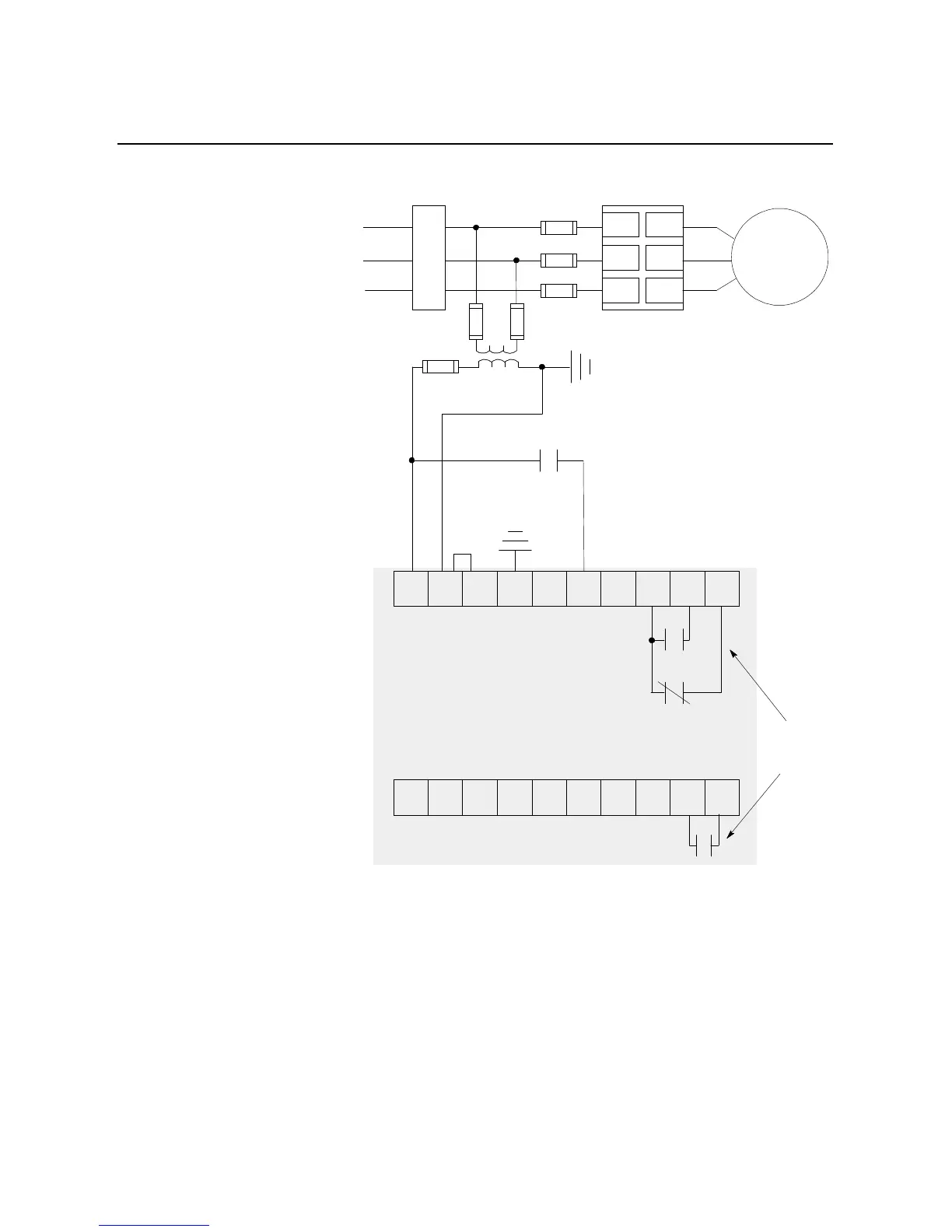
Figure 3.12 Typical Wiring Diagram for Two-Wire Control or Programmable
Control Interfacing
①
Customer supplied.
②
Refer to the controller nameplate to verify the rating of the control power input voltage.
Notes: (1) Programmable controller interfacing in this diagram refers to hard-wiring between the
PLC’s output contacts and the SMC Dialog Plus controller’s control terminals. For a
wiring diagram related to programmable controller interfacing via the SMC Dialog
Plus controller’s SCANport, refer to Figure 3.14.
(2) The OFF state leakage current for a solid-state device must be less than 6 mA.
Two-wire Device
➀
11 12 13 14 15 16 17 18 19 20
21 22 23 24 25 26 27 28 29 30
Internal
Auxiliary
Contacts
3-Phase
Input Power
Branch
Protection
➀
Fast-acting
SCR Fuses
(optional)
➀
SMC Dialog Plus
Controller
M
➀
L1/1
L2/3
L3/5
T1/2
T2/4
T3/6
➀
➀
➀
➁
SMC Dialog Plus
Control Terminals

 Loading...


