Wiring
3-13
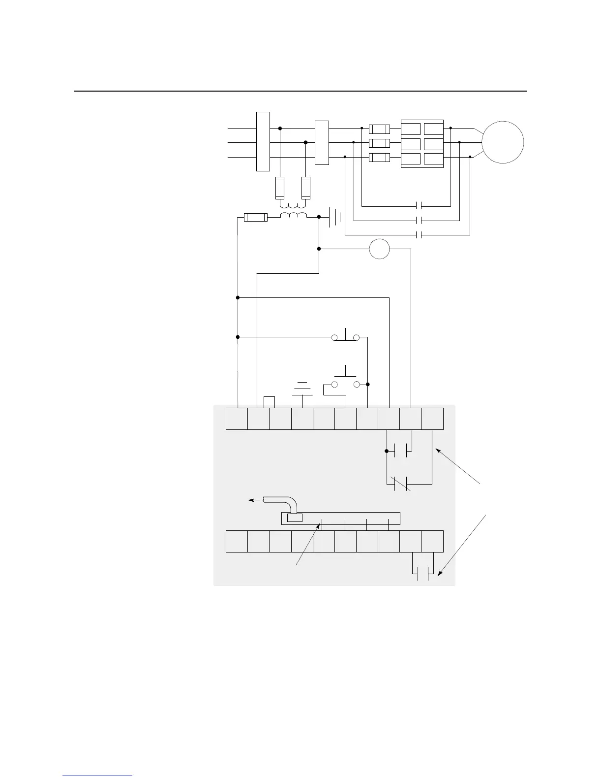
Figure 3.17 Typical Wiring Diagram for Bypass Applications
①
Customer supplied.
②
The Bulletin 825 Converter Module is required when the SMC Dialog Plus controller will be providing
motor overload protection during bypass operation.
③
Refer to the controller nameplate to verify the rating of the control power input voltage.
Stop
➀
Start
➀
3-Phase
Input Power
Branch
Bypass Contactor (BC)
➀
Protection
➀
Fast-acting
SCR Fuses
(optional)
➀
Bulletin 825
Converter
Module
➀ ➁
M
➀
BC
➀
➀
➀
➀
➂
L1/1
L2/3
L3/5
T1/2
T2/4
T3/6
11 12 13 14 15 16 17 18 19 20
21 22 23 24 25 26 27 28 29 30
Internal
Auxiliary
Contacts
Fanning Strip
➀
To
Bulletin 825
Converter
Module
Auxiliary
contacts set for
Up-to-speed
SMC
Dialog Plus
Controller
SMC Dialog Plus
Control Terminals

 Loading...


