Installation
2-9
Power Factor
Correction Capacitors
The controller can be installed on a system with power factor
correction (PFC) capacitors. The capacitors must be located on the
line side of the controller. This must be done to prevent damage to the
SCRs in the SMC Dialog Plus controller.
When discharged, a capacitor essentially has zero impedance. For
switching, sufficient impedance should be connected in series with
the capacitor bank to limit the inrush current. One method for
limiting the surge current is to add inductance in the capacitor’s
conductors. This can be accomplished by creating turns or coils in
the power connections to the capacitors.
• 250V – 6 inch diameter coil, 6 loops
• 480–600V – 6 inch diameter coil, 8 loops
Take care in mounting the coils so that they are not stacked directly on
top of each other; stacking will cause a canceling effect. Also, mount
the coils on insulated supports away from metal parts so they will not
act as induction heaters. If an isolation contactor is used, put
capacitors in front of contactor.
Note: For further instructions, consult the PFC capacitor vendor.
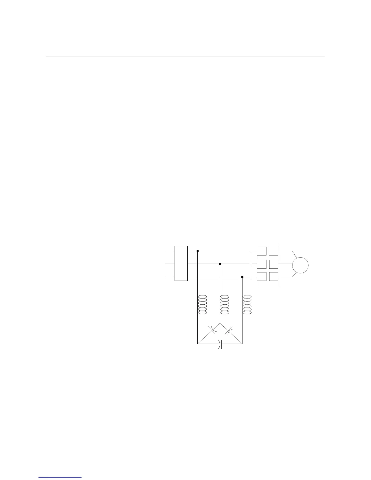
Figure 2.6 Typical Wiring Diagram for Power Factor Correction Capacitors
Power Factor
Correction Capacitors
SMC Dialog
Plus
Motor
Branch Circuit
Protection
➀
➀
Customer supplied
➁
Not required
IC
L1/1 T1/2
L2/3 T2/4
L3/5 T3/6
➀
➀
➀➀➀
➀
➁

 Loading...


