Chapter 3
Wiring
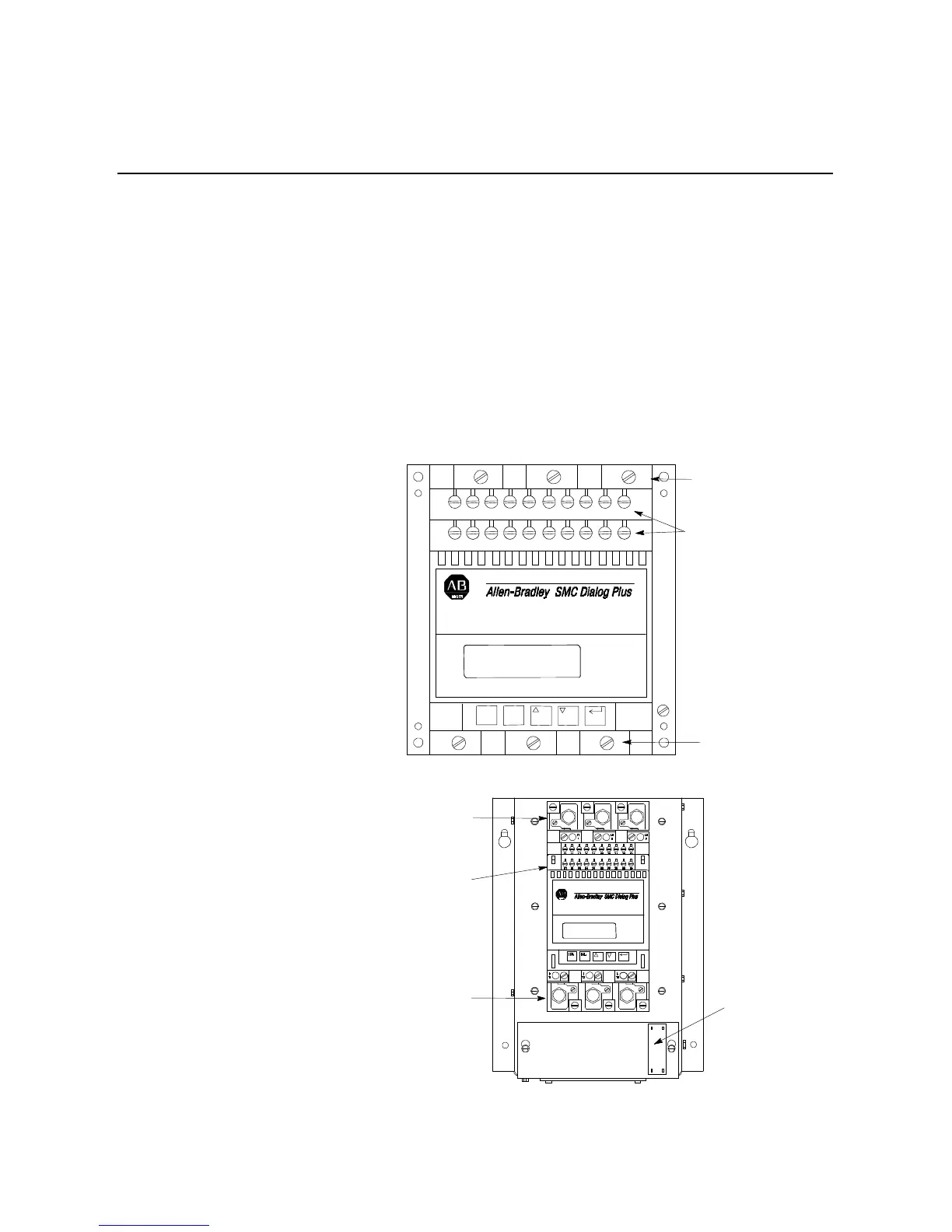
Terminal Locations
The SMC Dialog Plus controller wiring terminal locations are shown
in Figure 3.1 through Figure 3.4. Make wiring connections as
indicated in the typical connection diagrams. Connect the line to
terminals L1/1, L2/3, and L3/5. Connect the load to terminals T1/2,
T2/4, and T3/6. For controllers rated 24–135A, a grounding screw is
provided to ground the heatsink per applicable codes. For controllers
rated 180A–1000A, a grounding lug is provided on the mounting
plate.
Figure 3.1 Wiring Terminal Locations (24 to 54 Amp)
Figure 3.2 Wiring Terminal Locations (97 and 135 Amp)
Input Power
Connections
Control
Circuit
Connections
Output Power
Connections
L1
1
2
T1
4
T2
6
T3
ESC. SEL.
11
21
13
23
12
22
14
24
15
25
16
26
17
27
18
28
19
29
20
30
L2
3
L3
5
Input Power
Connections
Control
Circuit
Connections
Output Power
Connections
Fan
Power
Connections

 Loading...


