2-8
Installation
Mounting (cont.)
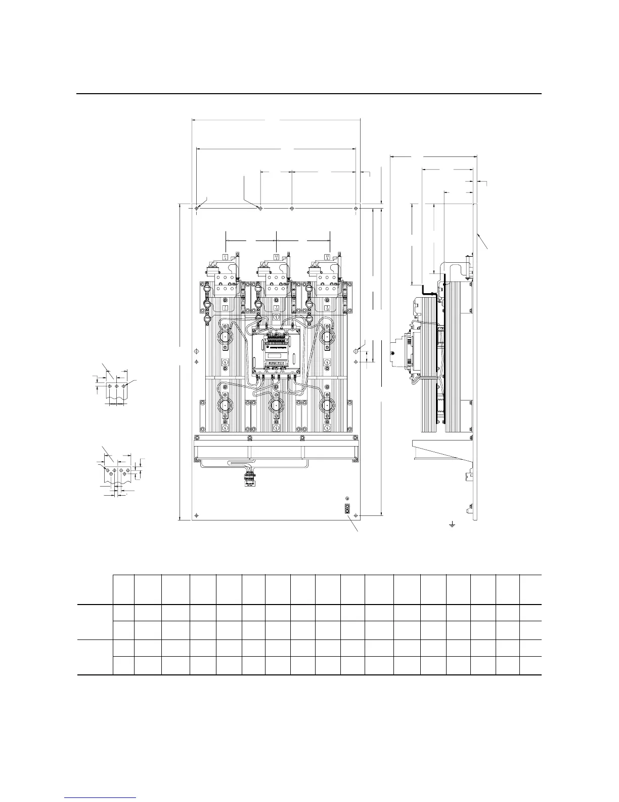
Figure 2.5 Dimensions: 650-1000 Amp Controllers
All dimensions are approximate and are not intended for manufacturing purposes. Refer to the nearest Allen-BradleyAllen-Bradley sales office for complete dimension
drawings.
Unit
A
Width
B
Height
C
Depth
DEFGHJ K L MNPQR
650 and
720A
Controller
mm 32.0 60.0 15.83 30.25 6.0 12.13 .875 .875 2.0 58.25 9.935 5.475 .75 329 317.5 246.1
in. 812.8 1524.0 402.1 768.35 152.4 308.0 22.22 22.23 50.8 1479.55 252.35 139.06 19.05 13 12.5 9.69
850 and
1000A
Controller
mm 32.0 60.0 15.83 30.25 6.0 12.13 .875 .875 2.0 58.25 9.935 5.475 .75 383 375 246.1
in. 812.8 1524.0 402.1 768.35 152.4 308.0 22.22 22.23 50.8 1479.55 252.35 139.06 19.05 15 14.75 9.69
.5 Dia. (Ø 12.7)
6 – Holes
.56 Dia. (Ø 14.2)
2 – Lifting Holes
D
A
G
Q
P
.105 Steel
Sheet
(2.67)
4.0
(101.6)
2.0
(50.8)
.688
(17.5)
.515
(13.1)
Dia. Typ.
1.312 (33.3)
650–720 Amp
.688
(17.5)
.67
(17)
.64
(16.3)
Typ.
.64
(16.3)
850–1000 Amp
5.0
(127)
2.5
(63.5)
Typical Line and Load Bus
.75 Dia.
(Ø 19.1)
2 – Holes
Grounding Lug
(wide range: #6 solid to 250 MCM stranded)
1.312 (33.3)
.64
(16.3)
H
C
L
M
T
B
K
J
N
E
F
R R

 Loading...


