2-6
Installation
Mounting (cont.)
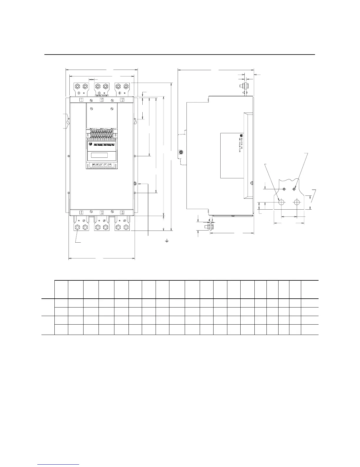
Figure 2.3 Dimensions: 180 through 360 Amp Controllers
All dimensions are approximate and are not intended for manufacturing purposes. Refer to the nearest Allen-Bradley sales office for complete dimension drawings.
Unit
A
Width
B
Height
C
Depth
D E F G H J K L M N P QRS
Approx.
Ship.
Wt.
180A
Cont.
mm 273 580 294.2 245 5 81 221 361 453 56 251 167 35 19.3 8.4 28 4.7 25 kg
in. 10.750 22.063 11.583 9.647 .207 3.195 8.695 14.195 17.817 2.213 9.880 6.562 1.375 .76 .250 1.1 .187 55 lbs.
240–
360A
Cont.
mm 273 580 294.2 245 5 81 221 361 453 56 251 167 35 19.3 8.4 28 4.7 30 kg
in.
10.750 22.063 11.583 9.647 .207 3.195 8.695 14.195 17.817 2.213 9.880 6.562 1.375 .76 .250 1.1 .187 65 lbs.
Terminal Detail
.136 (3.5) Dia.
#8-32 UNC-2B
.413 (10.5) Dia.
.984
(25)
.531
(13.5)
1.161
(29.5)
2.250
(57)
1.02
(25.9)
S
R
M
Q
N
C
B
J
H
G
F
E
P
D
A
180, 240, and 360 Amp
Dbl. Lug Mtg.
L
K
.281 (7.1)
Rad.
2 Key Holes
.281 (7.1)
Dia.
6 Mtg. Holes
Ground Nut
(1/4-20)

 Loading...


