10-6
Troubleshooting
Control Module Removal
The control module is not intended for field repair. The entire module
must be replaced if a failure occurs. Follow the applicable procedure
for control module removal.
24–135 Amp
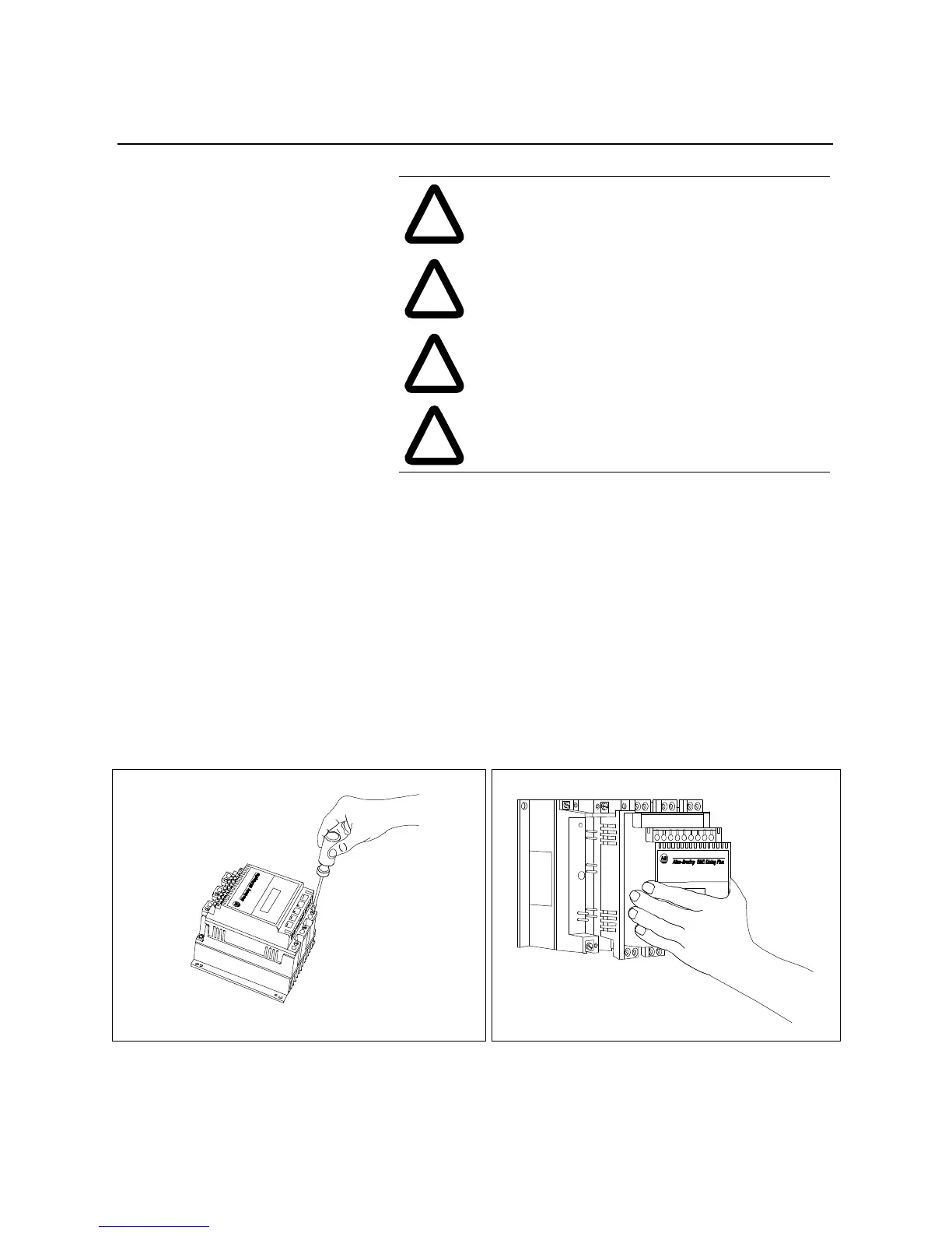
Refer to Figure 10.2 for control module removal reference.
1. Remove all control wires and serial port cables.
2. Loosen six mounting screws.
3. Unplug control module from the power structure by pulling
forward.
Figure 10.2 Removal of Control Module (24–135A)
!
ATTENTION: To avoid shock hazard, disconnect
main power before working on the controller, motor, or
control devices (such as Stop/Start push buttons).
!
ATTENTION: Make sure that wires are properly
marked and that programmed parameter values are
recorded.
!
ATTENTION: When removing control module, make
sure power module or interface board pins do not bend.
!
ATTENTION: The 500 amp device is equipped with
two shields that must be in place when power is applied
to the controller.

 Loading...


