8-28
Serial Communications
This indicates that the SMC Dialog Plus controller’s input data is
mapped to words 7 and 8.
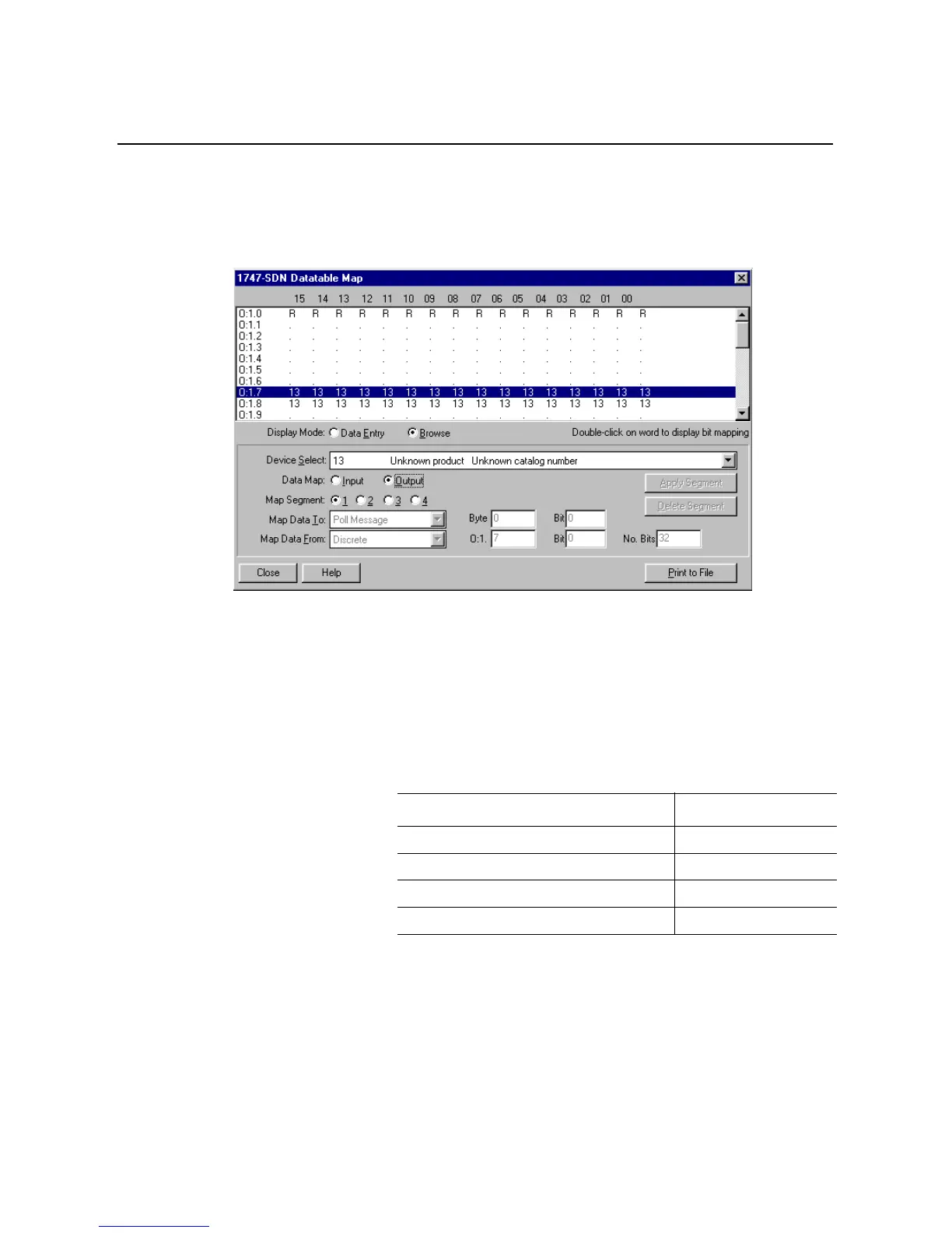
By clicking the radio button next to Output, the output data mapping
can be seen; the following screen will appear:
This indicates that the SLC-500’s output data associated with the
SMC Dialog Plus controller is mapped to words 7 and 8.
Given this data table mapping, following are the individual logic
command and status bit addresses for the SMC Dialog Plus
controller:
SMC Dialog Plus Controller Logic Command Addresses
①
①
Refer To Table 8.A
Bit Description Address
Stop O:1.7/00
Start O:1.7/01
Option Command O:1.7/02
Clear Fault O:1.7/03

 Loading...


