3-10
Wiring
Standard Controller
Wiring Diagrams (cont.)
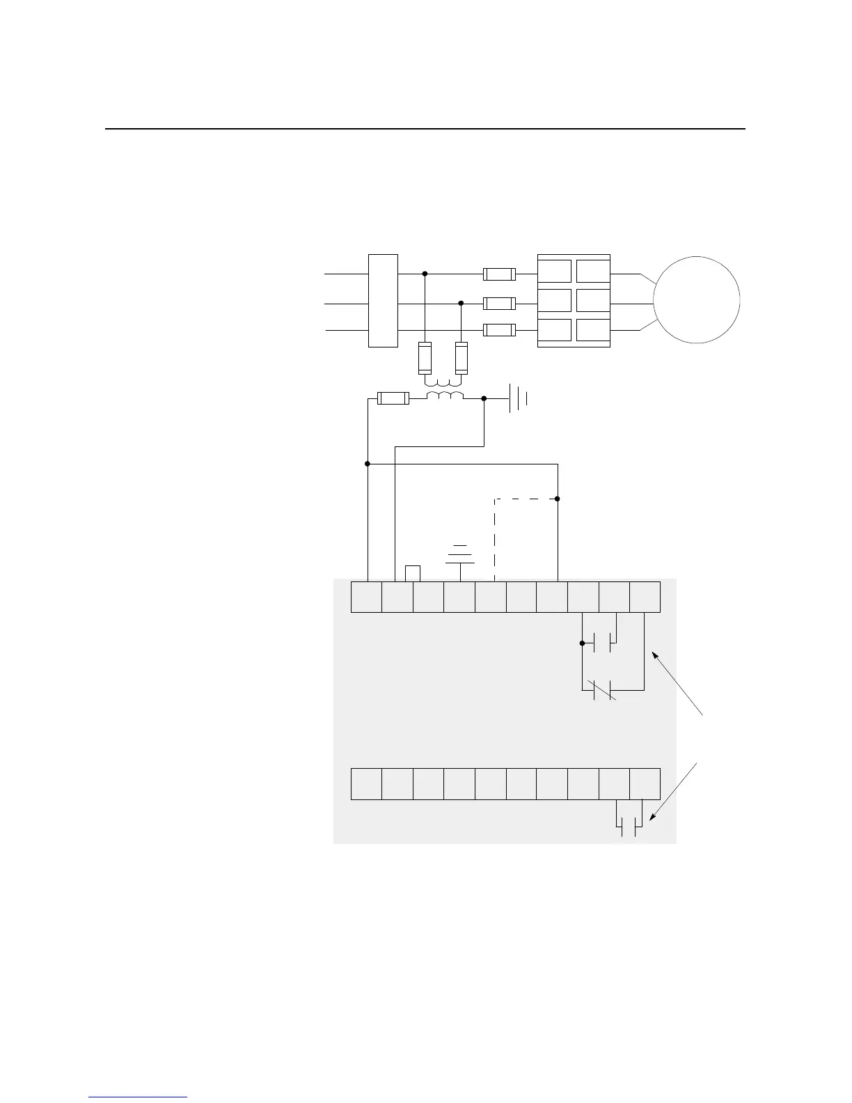
Figure 3.14 Typical Wiring Diagram for Start-Stop Control via the SCANport
Note: Use this wiring diagram when start-stop will come from
either a Bulletin 1201 human interface module or a Bulletin
1203 communication module connected to the SMC Dialog
Plus controller’s SCANport.
①
Customer supplied.
②
If the Soft Stop, Pump Control, or the SMB Smart Motor Braking option is installed, place additional
jumper to terminal 15.
③
Refer to the controller nameplate to verify the rating of the control power input voltage.
11 12 13 14 15 16 17 18 19 20
21 22 23 24 25 26 27 28 29 30
Internal
Auxiliary
Contacts
3-Phase
Input Power
Branch
Protection
➀
Fast-acting
SCR Fuses
(optional)
➀
M
➀
L1/1
L2/3
L3/5
T1/2
T2/4
T3/6
➀
➀
➀
➁
➂
SMC Dialog Plus
Controller
SMC Dialog Plus
Control Terminals

 Loading...


