Effectivity: 914 Series
Edition 2 / Rev. 0
d04280
page 91
July 01/2008
BRP-Rotax
INSTALLATION MANUAL
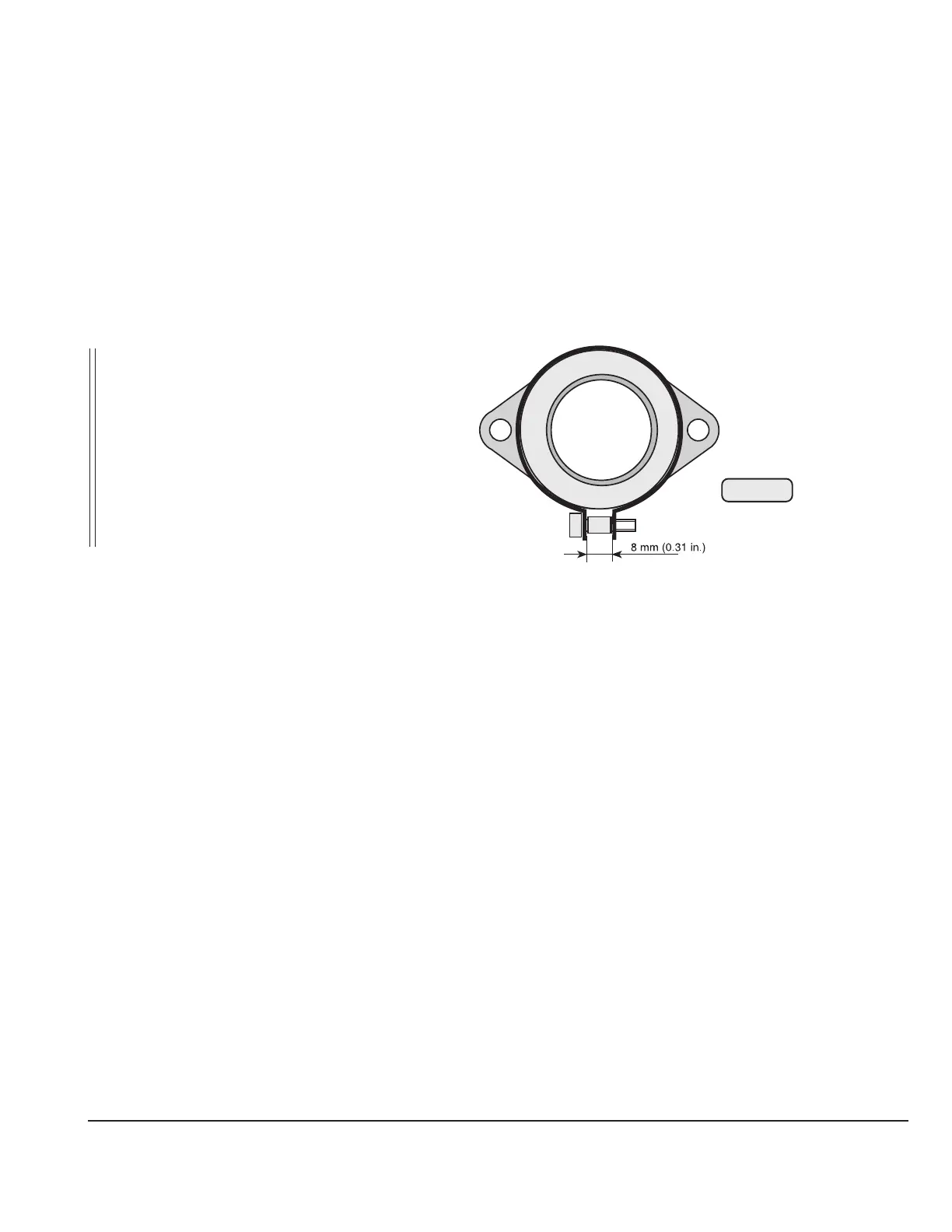
15) Carburetor
See Fig. 53.
The carburetors on the standard engine are already attached by a flexible flange. Only
connections of the Bowden cable for throttle and starting carb have to be established.
It is recommended, to make the adjustment of the Bowden cable after engine installation has
been completed, to ensure exact final adjustment.
■ CAUTION: In case this has not been taken care of, verification of the throttle position is
required prior to the trial run. Refer to section 15.5.
15.1) Requirements on the carburetor
See Fig. 54.
The carburetors are positioned above the exhaust sockets. Below the carburetors one
each drip tray (1) with a draining connection (2) is fitted which serves as a heat shield
as well.
▲ WARNING: In the area of the float chamber the temperature limit of the fuel must
not be exceeded.
If necessary install additional insulation or heat shields. Certification to
the latest requirements such as FAR or EASA has to be conducted by
the aircraft manufacturer.
Fig. 53
08414

 Loading...


