Effectivity: 914 Series
Edition 2 / Rev. 0
d04277
page 59
July 01/2008
BRP-Rotax
INSTALLATION MANUAL
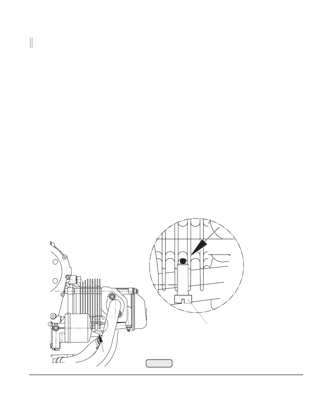
Schraube / screw M5
02050
Fig. 29
12.10)Coolant capacity
4 cylinder heads: .......................... 560 cm
3
(34.1 in
3
)
water pump: ................................. 100 cm
3
(6.10 in
3
)
expansion tank: ............................ 250 cm
3
(15.2 in
3
)
2 m coolant hose
(18 mm (.71 in) inside dia.) : ....... 500 cm
3
(30.5 in
3
)
total coolant quantity in engine: ............. approx. 1,5 l
(0.4 gal (US))
12.11)Cooling air ducting
Contrary to the cylinder heads, the cylinders are ram air cooled. Plan cooling air
ducting according to installation requirement.
▲ WARNING: The cooling air ducting has to be designed and built such, that the
operating temperatures are kept within the specified limits and
maximum values are not exceeded.
This must also be warranted at "hot day conditions"!
Max. permissible cylinder wall temperature on cylinder 2 ............. 200 °C (392 °F)
(see Fig. 29)

 Loading...


