Effectivity: 914 Series
Edition 2 / Rev. 0
d04279
page 87
July 01/2008
BRP-Rotax
INSTALLATION MANUAL
M5
M4
P1
P2
11,75
0,46 in.
8
0,32 in.
11
0,43 in.
ø 38
ø1,5 in.
ø 13,3
ø0,52 in.
ø 12
ø0,47 in.
22
0,87 in.
141,5(
±3)
5,57(±0.12)in.
20(
±0,5)
0,79(
±0.02)in.
30
1,18 in.
ø 9
ø0,35 in.
ø 8
ø0,32 in.
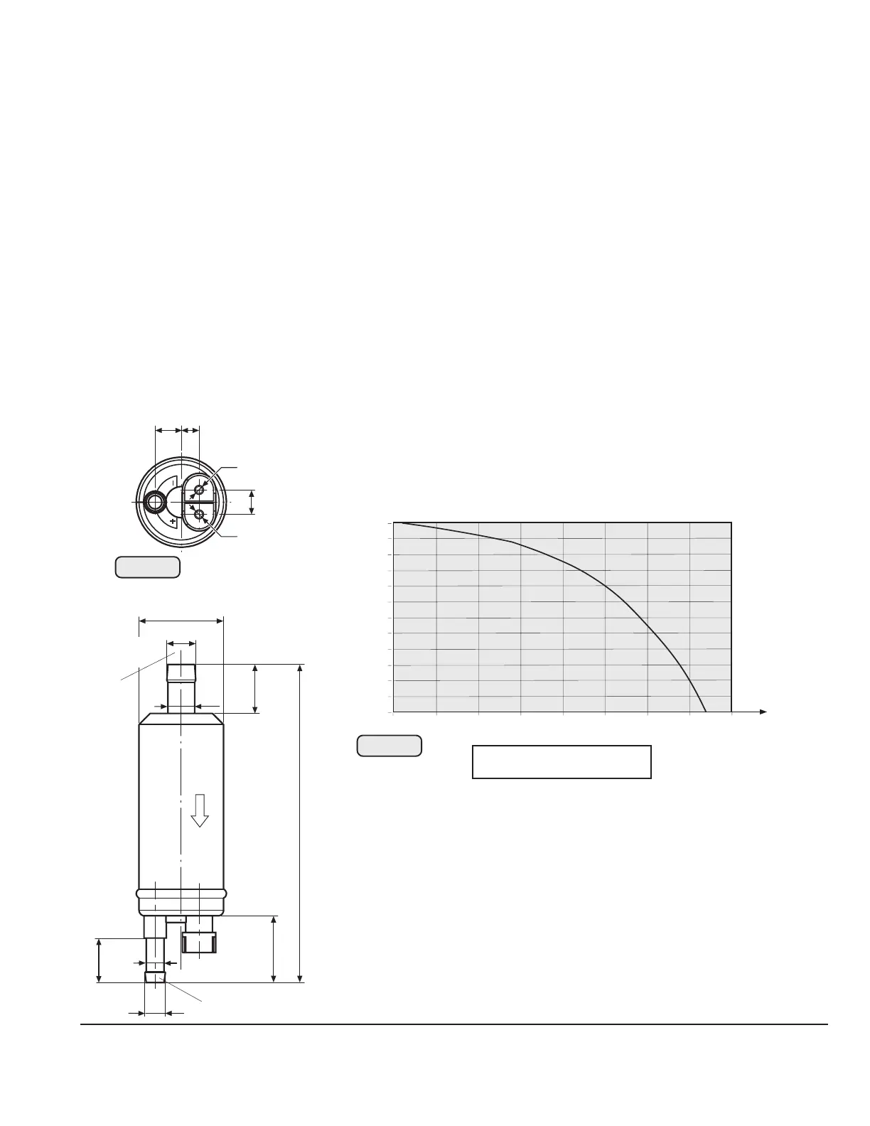
14.4) Connecting dimensions, location of joints and directives for installation
14.4.1) Electric fuel pump
See outline of fuel pump (2), Fig. 48, 49 and 50.
Design: self priming vane pump
Volume of supply: electric fuel pump with attachment kit, 2 hose clamps and
various attachment elements
Weight: 0,35 kg (.8 lb) inclusive attachment items
Fitting position: horizontal or vertical
Engine start, operating temperature: -25 °C (-13 °F) - 50 °C (120 °F)
Connections: See Fig. 49.
Inlet (1) (suction side)
Outlet (2) (pressure side)
■ CAUTION: Utilize the complete slip-on length on all hose connections. Secure
fuel hoses with suitable spring type clamp or screw clamp.
Delivery rate/pressure : See diagram Fig. 50.
Fig. 49
Δ
P= P2 – P1
The diagram shows the delivery rate of the electric fuel pump over
pressure.
Take note of the following:
- diagram outlines min. capacity at nominal voltage
on pump
- pressure and suction head are "ZERO"
- graph is effective on the seasoned pump only,
running-in period approx. 30 min.
◆ NOTE: A capacity increase of approx. 20% is feasible by running-
in process.
02473
P
0
10
20
30
40
50
60
70
80
90
100
110
120
0
250 500 750 1000 1250 1500
1750 2000 hPa
l/h
0
26,41
29,05
31,70
US gal/h
2,64
5,28
7,92
10,56
13,20
15,85
18,49
21,13
23,77
05085
Δ
1
2
Fig. 50

 Loading...


