page 106
July 01/2008
Effectivity: 914 Series
Edition 2 / Rev. 0
d04281
INSTALLATION MANUAL
BRP-Rotax
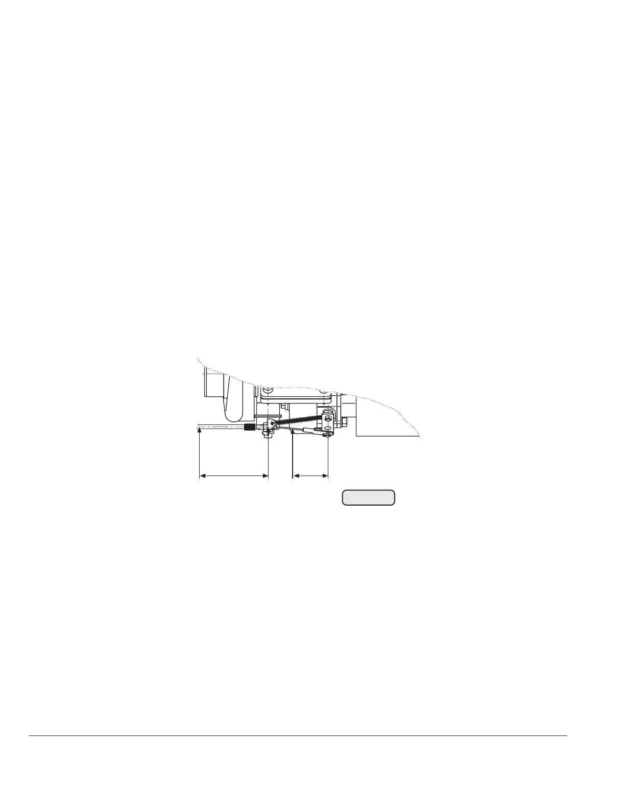
Fig. 68
02617
65 mm
(2,6 in.)
35 mm
(1,4 in.)
2
1
3
18.2) Servo cable
- bending radius: min. 50 mm (2")
Following temperatures must be measured on the positions set out in figure 51a and
must not be exceeded during take-off and after engine stop (heat accumulation).
Pos. Description Temperature
(1) cable conduit max. 120 °C (250 °F)
(2) cable support max. 120 °C (250 °F)
(3) wire rope max. 140 °C (284 °F)
■ CAUTION: All temperature limits must be verified at the first time of installation of
the ROTAX 914 into an airframe, or at any modification of the airframe
as it may influence such temperatures.

 Loading...


