page 114
July 01/2008
Effectivity: 914 Series
Edition 2 / Rev. 0
d04282
INSTALLATION MANUAL
BRP-Rotax
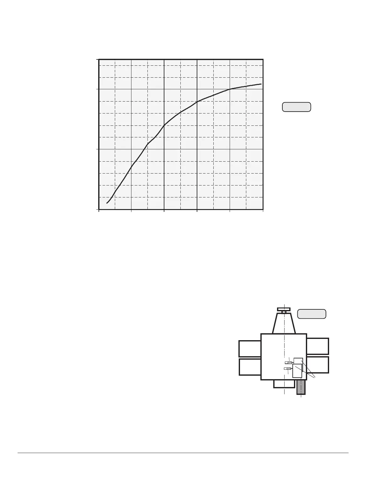
0
10
20
1000 2000 3000 4000 5000 6000
(A)
(1/min.)
19.4.3) Electronic modules
See Fig. 4 Pos. 25 and Fig.73
Ambient temp. for the electronic modules (1): max. 80 °C (176 °F).
19.4.4) Ignition switches (on-off switch)
See Fig. 73 and 75.
- type: two separate, suitable on-off
switches (Fig. 69, pos. (33))
- switching voltage: min. 250 V
- switching current: min. 0,5 A
Wires from the ignition switches connect to
the electronic module (see Fig. 73)
- one each flexible wire 0,75 mm
2
(18
AMG) brown,
length approx. 35 mm (1 3/8") beginning at elec-
tronic module with one each plug socket and
insulating sleeve 3,96 mm. At the new version the cable grommet and
fasten connector are integrated in the 6-pole connector housing. See also
SI-914-016, latest issue.
Fig. 72
02500
br
br
B
A
Cyl. 1
Cyl. 3
Cyl. 2
Cyl. 4
Fig. 73
02501
1

 Loading...


