page 116
July 01/2008
Effectivity: 914 Series
Edition 2 / Rev. 0
d04282
INSTALLATION MANUAL
BRP-Rotax
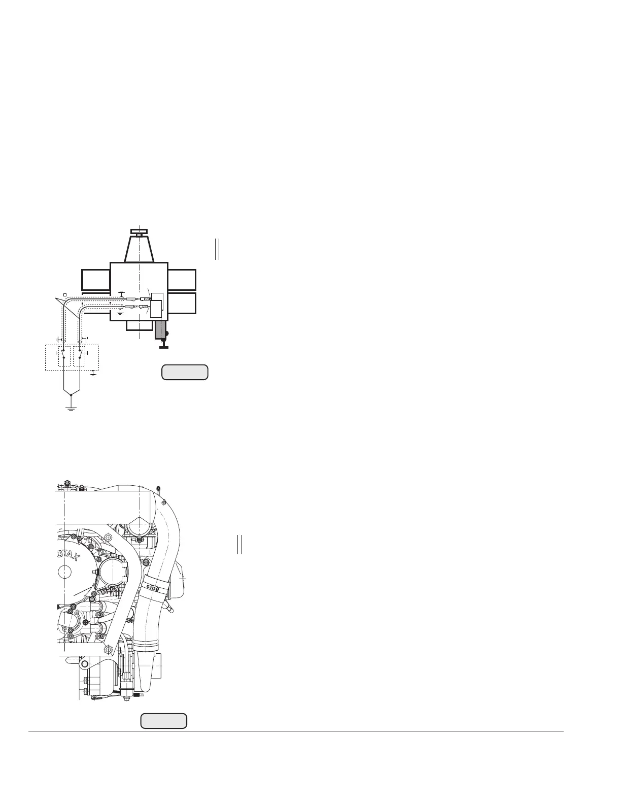
19.4.5) Electric starter
See Fig. 76.
Wire from starter relay to the electric starter
- cross section of at least 16 mm
2
(6 AWG)
- output: 0,7 kW / 0,9 kW optional
- positive terminal (1): M6 screw (tightening torque 4
Nm (35 in.lb)) suitable for ring terminal to DIN 46225
(MIL-T-7928); PDIG or equivalent
- grounding: via engine block
■ CAUTION: Suitable for short starting periods only.
■ CAUTION: Max. 80 °C (176 °F) temperature range by the
electric starter housing. Activate starter for max.
10 sec. (without interruption), followed by a cooling
period of 2 min!
0,75
br
br
B
A
07602
Fig. 75
- Wire of top electronic module (marked "A") for ignition circuit A.
- Wire of bottom electronic module (marked "B") for ignition circuit B.
◆ NOTE: Ignition circuit A controls: top spark plugs of cylinder 1 and 2;
lower spark plugs of cylinder 3 and 4.
Ignition circuit B controls: top spark plugs of cylinder 3 and 4;
lower spark plugs of cylinder 1 and 2.
■ CAUTION: The electromagnetic compatibility (EMC) and electromag-
netic interference (EMI) depends essentially on the wire used.
See Fig. 75.
Min. section area: 2x 0,75 mm
2
(18 AWG) (shielded flexible
cable, shielding braid (low-resistance) on both ends grounded
to prevent EMI (e.g. specification MIL-27500/18).
No or insufficient shielded cables can cause engine shut-off
due to electromagnetic and radio interference.
The metal base of each ignition switch must be grounded to
aircraft frame to prevent EMI.
Fig.76
02502
1

 Loading...


