page 68
July 01/2008
Effectivity: 914 Series
Edition 2 / Rev. 0
d04278
INSTALLATION MANUAL
BRP-Rotax
13.5) Connecting dimensions and location of connections
■ CAUTION: Utilize the full slip-on length for hose connections. Secure hoses with
suitable screw clamp or by crimp connection.
◆ NOTE: The oil pipeline connections are optional as UNF-thread.
See SI-914-005.
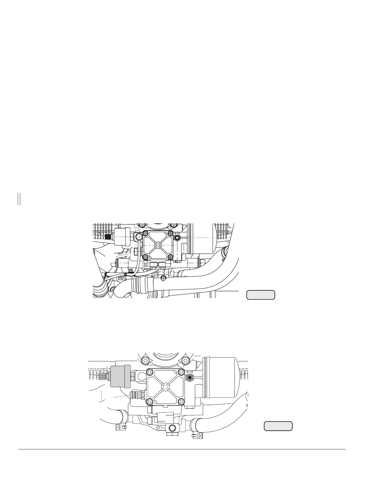
13.5.1) Oil circuit (engine)
See Fig. 37, 38, 39 and 40.
Depending on engine certification, the oil pump inlet connector s can vary:
- 914 F ......... thread M18 - optional UNF (AN)-thread
- 914 UL ....... inlet nipple - optional M18 or UNF (AN)-thread
Oil pump (inlet) (1) .................. thread M18 x 1,5 x 11
◆ NOTE: Suitable for use of a swivel joint. See fig. 42.
Tightening torque:..................... 25 Nm (18.5 ft.lb)
Fig. 37
02468
TO
Fig. 38
00226
Oil pump inlet nipple (2): outside dia .......... 13,2 mm (0.52 in.)
slip-on length ...... max. 21 mm (0.83 in.)
1
2

 Loading...


