Effectivity: 914 Series
Edition 2 / Rev. 0
d04281
page 105
July 01/2008
BRP-Rotax
INSTALLATION MANUAL
1
Fig. 66
04853
6,5
R12
60
2,36 in.
37
1,57 in.
60
2,36 in.
14
0,55 in.
R12
14
0,55 in.
2,5
0,01 in.
12
0,47 in.
15
0,59 in.
91
3,58 in.
61
2,4 in.
42
1,65 in.
35
1,38 in.
70
2,76 in.
Fig. 67
02494
1
2
3
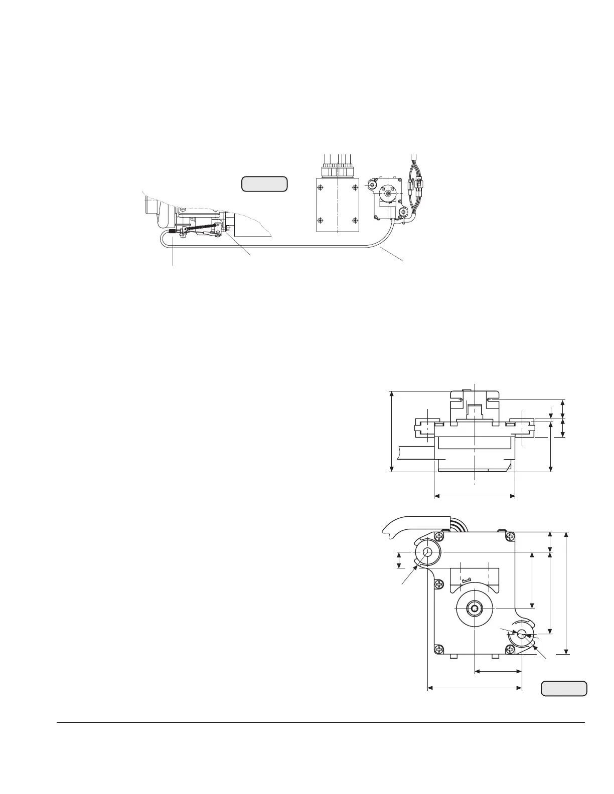
18) Servo motor/Servo cable
See Fig. 66/67.
The correct adjustment of the servo cable (1) and consequently the waste gate (2) was made
already on the course of the testrun at BRP-Rotax.
18.1) Servo motor
Prior to engine operation check the position of the waste gate as follows:
▲ WARNING: Engine stop - ignition "OFF".
- Check of the waste gate accordance with the Maintenance Manual 914 F.
Additionally, only the actual attaching of the
servo motor has to be performed.
- operating temperature:
min. - 20 °C (- 4 °F)
max. +60 °C (140 °F)
- dimensions and attachment:
see sketch (Fig. 67)
- location of installation:
vibration neutralized place
▲ WARNING: Installation in the engine
compartment is not permit-
ted since the servo motor is
not of a fire resistant con-
struction.
A recommendable location is
in the cockpit below the instru-
ment panel.
◆ NOTE: Place of installation is limited
by the length of the servo ca-
ble.
- location of installation:
approx. 1000 mm (40") from waste gate

 Loading...


