page 24
July 01/2008
Effectivity: 914 Series
Edition 2 / Rev. 0
d04275
INSTALLATION MANUAL
BRP-Rotax
6 ignition housing
7 ignition cover
8 constant depression carb
9 airbox
10 engine suspension frame
11 stainless steel exhaust
system
12 turbocharger
13 turbo control unit (TCU)
14 fuel pressure control
15 servo motor
16 servo cable
17 cable assembly
18 coolant pump
19 expansion tank
20 2 separate oil pumps
21 connection for oil return
line (engine)
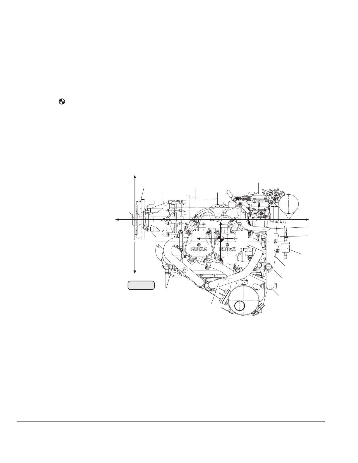
7.3) Engine components, engine views, definition of main axes
See Fig. 2/3/4/5/6.
PTO power take off side
MS magneto side
A points of attachment for engine transport
centre of gravity
P zero reference point for all dimensions
◆ NOTE: Allow ±1 mm on all stated dimensions as manufacturing tolerance
x,y,z axes for system of coordinates
Cyl.1 Cylinder 1 Cyl.3 Cylinder 3
Cyl.2 Cylinder 2 Cyl.4 Cylinder 4
1 engine number
2 propeller flange
3 propeller gear
4 vacuum pump or hydraulic
governor for constant speed
propeller
33 connection for additional
temperature sensor (airbox)
34 drip tray
35 water trap
36 three way solenoid valve
37 2x electric fuel pump
38 oil tank
39 external alternator
40 enrichment jet
22 connection for oil return line (turbo)
23 oil filter
24 electric starter
25 electronic modules for ignition
26 compensation tube
27 connection for manifold pressure
28 sensor for oil pressure
29 sensor for oil temperature
30 sensor for cylinder head temperature
31 2x pressure sensor
32 connection for mechanical tachom-
eter
+z
-z
+x
-x
P
+z1
-x1
+x1
-z1
A
AS
00120
21
Fig. 2
MS
2
3
4
8
20
10
18
7
35
24
34
32
5 intake manifold

 Loading...


