Effectivity: 914 Series
Edition 2 / Rev. 0
d04276
page 35
July 01/2008
BRP-Rotax
INSTALLATION MANUAL
10.2) Permissible fitting positions
See Fig. 9/10/11.
To simplify the matter, reference is made only to the 2 engine attachment points R1,
L1 and the 2 turbo charger attachment points R(T)2 and L(T)2.
Location of the 2 turbo charger attachment points R(T)2 und L(T)2.
◆ NOTE: All dimensions to point of reference (P) and the system of coordi-
nates remain unchanged.
The following details of engine position are with reference to aircraft on ground,
ready for take off.
- engine suitable for propeller in tractor or pusher arrangement,
- propeller shaft above cylinders. See Fig. 2.
▲ WARNING: For upside down installation of the engine, the lubrication system,
fuel system and the cooling system are unsuitable!
Longitudinal axis:
- The centre of the attachment points L1 and L(T)2 must be on axis x2 parallel to
the x axis.
Allowable pitch deviation of parallelism of axes:
max. 6° counter-clockwise, on ground
max. 10° counter-clockwise, in operation
max. 30° clockwise (See Fig. 9)
▲ WARNING: On installations with fuel tank located above carburetor level com-
bined with badly closing carb float valve, fuel could pass into cylinders
at more than 6° decline of propeller shaft axis after longer periods of
downtime. See FAR, § 33.17.
▲ WARNING: Tighten all engine suspension screws as specified by the aircraft
manufacturer.
04862
04861
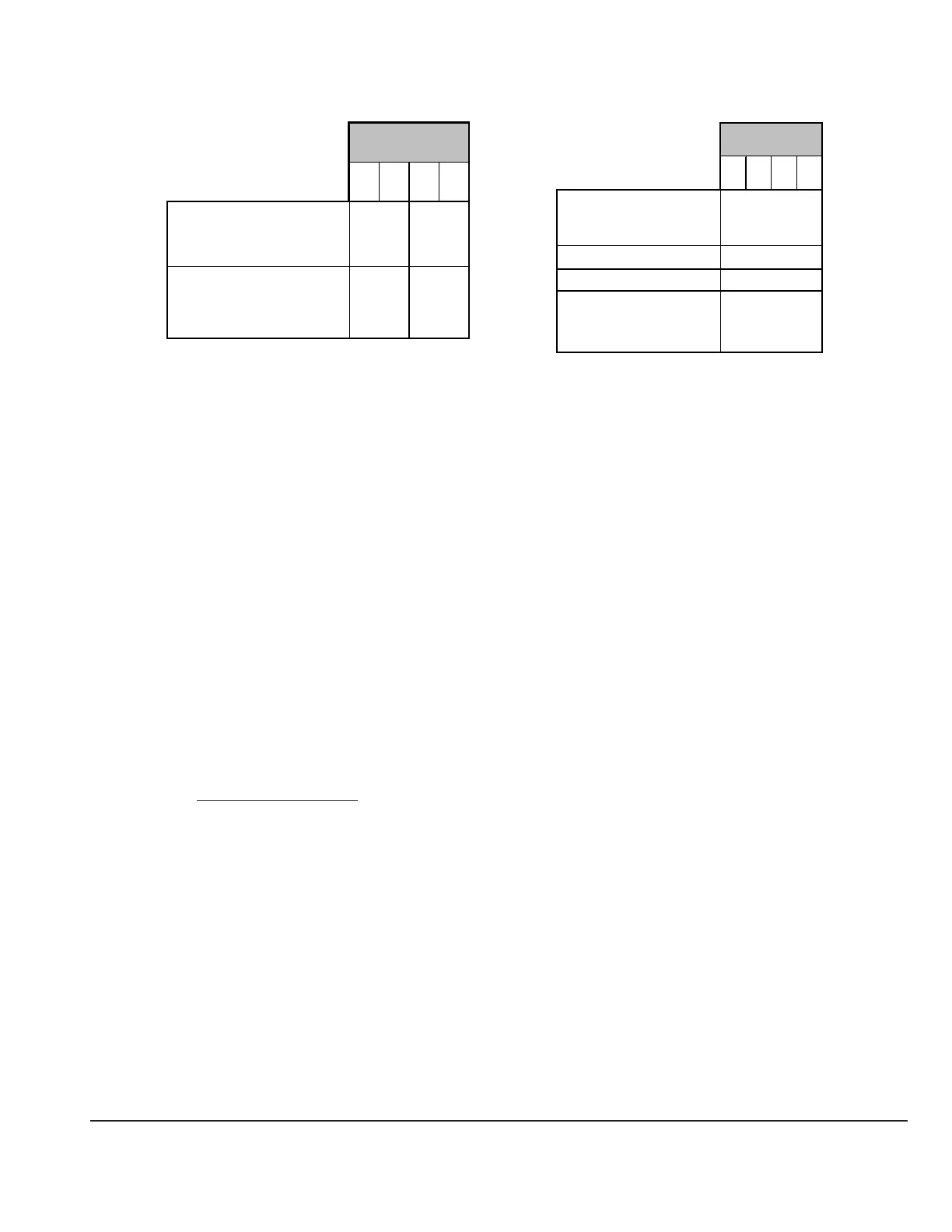
attachment point
L1 R1 L4 R4
max. allowable forces
(limit load) in (N) in x, y
and z axis
5000 1900
max. allowable bending
moment (limit load) in
(Nm) in x, y and z axis
77 39
attachment point
L2 R2 L3 R3
max. allowable forces
(limit load) in (N)
in x axis
5 000
in y axis 2 000
in z axis 3 000
max. allowable bending
moment (limit load) in (Nm)
in x, y and z axis
100

 Loading...


