page 118
July 01/2008
Effectivity: 914 Series
Edition 2 / Rev. 0
d04282
INSTALLATION MANUAL
BRP-Rotax
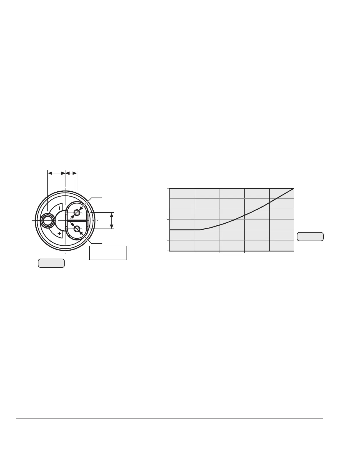
19.4.7) Electric fuel pumps
See Fig. 78/79.
- installation: see fuel system, section 14
- voltage: 12 V/DC
- connections: + terminal: M 4 screw connection
-
terminal: M 5 screw connection
suitable for ring terminals to DIN 46225
For radio interference suppression a capacitor (Fig. 69 Pos. (41)) of 1µF /
100 V has to fitted as near as possible to the terminals.
▲ WARNING: The certification to the latest requirements such as FAR or
EASA has to be conducted by the aircraft manufacturer.
- current input:
The current input per fuel pumps
by one fuel pump ~ 1,7 A
by two fuel pumps (Series) ~ 1,5 A
The diagram shows the current input over pressure.
Take note of the following:
- The diagram outlines minimum capacity at nominal voltage on pump.
- Pressure- and suction head are "ZERO".
- Graph is effective on a seasoned pump only, running-in period
approx. 30 min.
- Fuse:
Each of the two fuel pumps has to be protected by y slow blowing 5A fuse
in accordance with wiring diagram (Fig. 69).
11,75
0,46 in.
8
0,32 in.
11
0,43 in.
M5
M4
+
Anschluß
connector
Fig. 78
1,5
2,0
2,5
3,0 A
250
500
750
1250 hPa
0
1000
05120
02505
Δ
p
Fig. 79

 Loading...


