EasyManuals Logo

Rotax 914 series Installation Manual

Rotax 914 series
142 pages
To Next Page IconTo Next Page
To Previous Page IconTo Previous Page
Page #103 background imageLoading...
Page #103 background image
Effectivity: 914 Series
Edition 2 / Rev. 0
d04281
page 103
July 01/2008
BRP-Rotax
INSTALLATION MANUAL
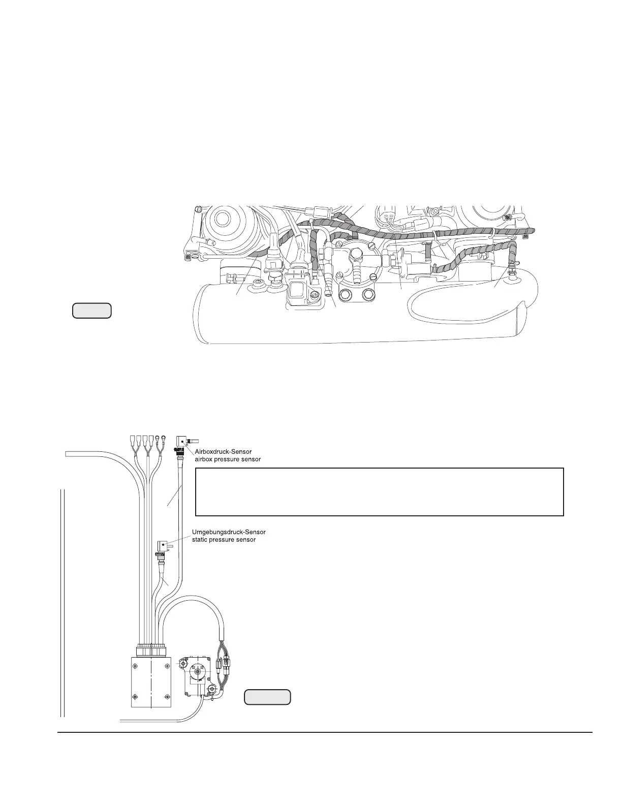
17) Pressure sensors
See Fig. 63/64.
2 pressure sensors are included in the supply volume of the engine and connected by plugs
with the wiring harness.
WARNING: Since a failure of pressure interconnections (1) of airbox, float chambers, fuel
control and pressure sensor would possibly result in an engine stop all these
interconnections have to made very carefully.
1
1
1
1
1
Fig. 64
08417
3
2
Fig. 63
05740
NOTE: To avoid any mix-up of pressure sensor wiring, plug connections are colour
coded.
grey plug connection (2) static pressure sensor
black plug connection (3) airbox pressure sensor

Table of Contents

Other manuals for Rotax 914 series

Questions and Answers:

Question and Answer IconNeed help?

Do you have a question about the Rotax 914 series and is the answer not in the manual?

Rotax 914 series Specifications

General IconGeneral
Bore79.5 mm
Stroke61 mm
Compression Ratio9.0:1
Cooling SystemLiquid-cooled cylinder heads, air-cooled cylinders
Redline5800 rpm
Engine Type4-cylinder, 4-stroke
Fuel TypeAvgas 100LL
Oil SystemDry sump
Fuel Systemfuel injection
TBO (Time Between Overhauls)2000 hours
Displacement1.211 liters (1211 cc)
Power Output84.6 kW (115 hp) at 5, 800 rpm

Related product manuals