Effectivity: 914 Series
Edition 2 / Rev. 0
d04278
page 65
July 01/2008
BRP-Rotax
INSTALLATION MANUAL
13.3) Checking of the lubrication system
To control the proper function of the lubrication system the following readings have to
be taken on the running engine.
◆ NOTE: The required pressure gauges and connection parts are not included
in the ROTAX engine delivery.
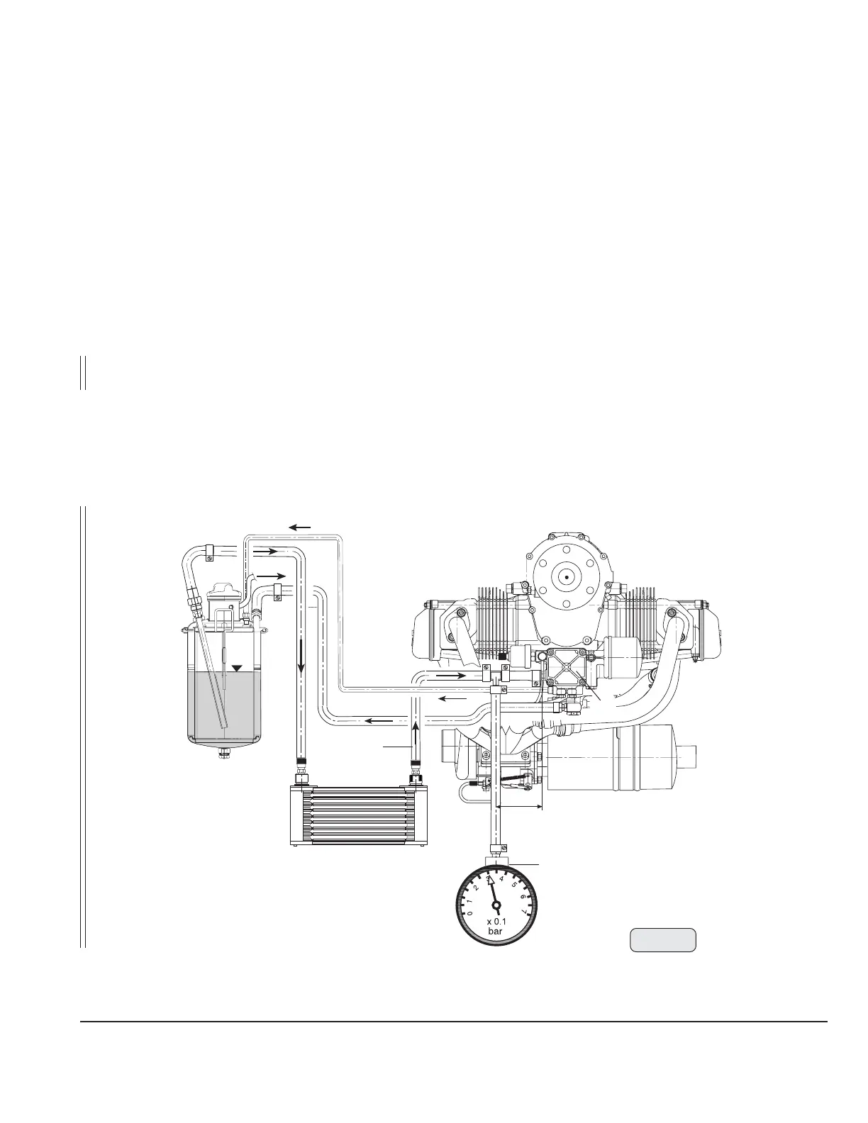
13.3.1) Measuring of the vacuum
Measuring of vacuum in the oil suction line (1) (line from oil tank to oil pump via
oil cooler) at a max. distance of 100 mm (4 in) from pump inlet (2).
At take-off performance the indicated vacuum (3) must not be more than 0,3
bar (4,35 psi) otherwise the oil hose (1) could colapse and thus blocking the oil
supply to the engine (See Fig 34).
▲ WARNING: The vacuum (3) must be verified over the total range of engine
operation (pressure gauge filled with liquid). Specially on cold
oil temperature the flow resistance increases, so that not
enough oil can flow on suction side.
max. 0,3 bar below atmospheric pressure
Fig. 34
08412
2
3
1
max. 100 mm
or 4 inch.

 Loading...


