Effectivity: 914 Series
Edition 2 / Rev. 0
d04283
page 137
July 01/2008
BRP-Rotax
INSTALLATION MANUAL
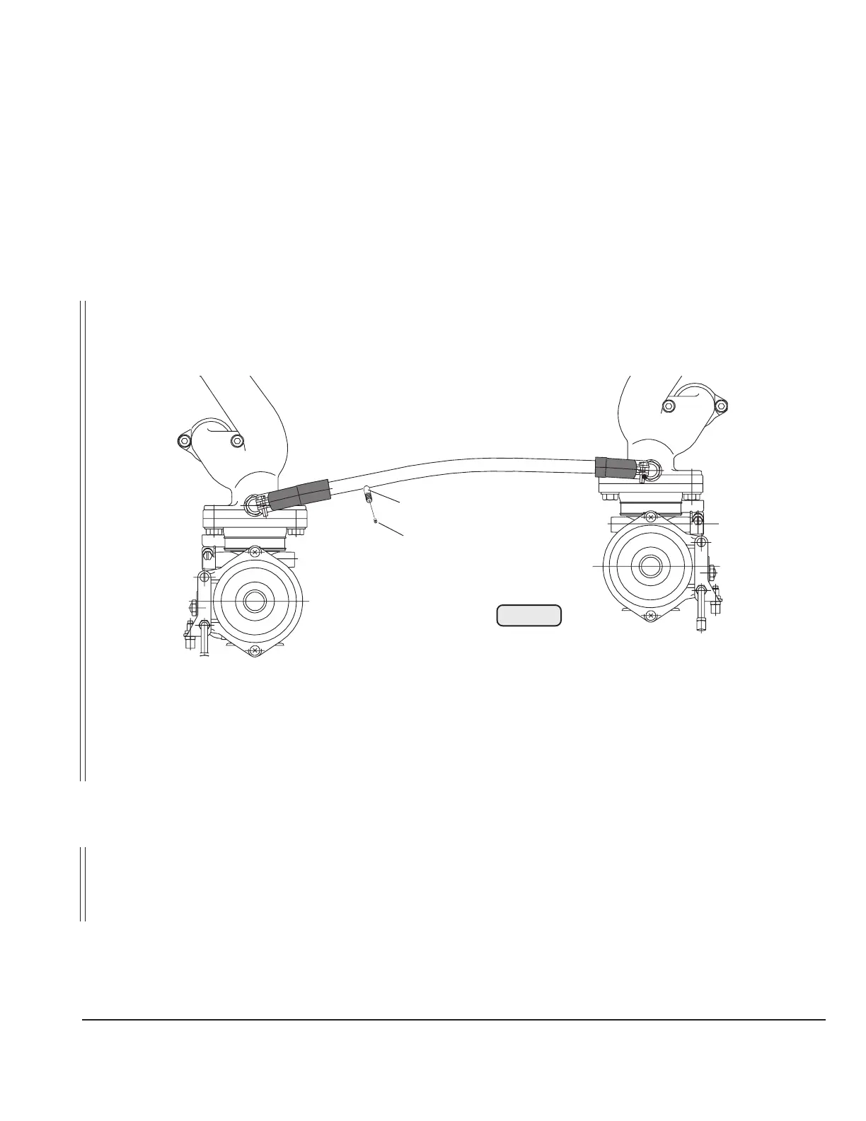
23.5) Monitoring of the intake manifold pressure
See Fig. 97.
Connection nipple (1) to measure manifold pressure:
outside dia. ø .................................. 6 mm (1/4")
slip-on length ................................... max. 17 mm (11/16")
■ CAUTION: Utilize the total slip-on length on all joints. Secure hose by suitable screw
clamps or crimp connection.
Fig. 97
08423
1
2
▲ WARNING: The connecting nipple is sealed with a screw of type M3.5x6 (2). If
this connecting nipple is needed the screw has to be removed.
■ CAUTION: Flawless operation of the indicating instrument needs the installa-
tions of a water trap between engine and instrument for the fuel
condensate.
◆ NOTE: For in-flight variable pitch propellers and constant speed propellers
a manifold pressure gauge must be fitted permanently in the
cockpit.

 Loading...


