Effectivity: 914 Series
Edition 2 / Rev. 0
d04277
page 55
July 01/2008
BRP-Rotax
INSTALLATION MANUAL
◆ NOTE: For proper operation keep hose to overflow bottle as short and small
as possible.
■ CAUTION: To warrant the proper operation of the cooling system the delivery
head between overflow bottle and expansion tank must not exceed
250 mm (10").
Requirements on the overflow bottle (7)
- transparent material
- unaffected by temperatures from - 40 °C (- 40 °F) to +125 °C (257 °F)
- resistant against 100% Glycol and any other anti freeze agent
- volume approx. 0,5 l (.13 US gal)
- possible to vent (6), diameter 2.5 mm (0.1 in.)
◆ NOTE: See therefore SB-914-025 "Modifications of the overflow bottle", latest
issue.
◆ NOTE: The overflow bottle ought to be furnished with a label indicating function
and content.
▲ WARNING: Ensure that the overflow bottle will never be empty, otherwise air will
be sucked into cooling circuit with a negative effect to safe operation
of the engine.
■ CAUTION: The overflow bottle and their supply lines and discharge lines should
never be installed in the area near the exhaust system, under specific
circumstances leaking coolant can be inflammable.
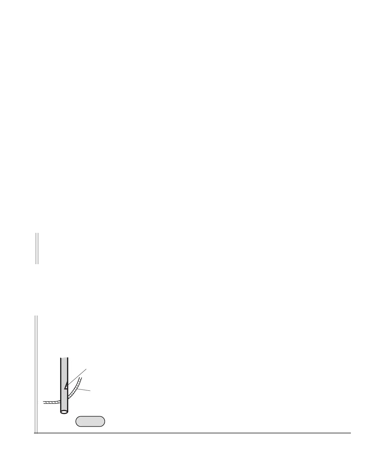
◆ NOTE: To enable an improved vent of the escaping coolant steam from the
expansion bottle in case of overheating, the plastic plug can be
retrofitted with hose nipple and hose.
The vent line (5) has to be routed in a way that no coolant can get in
contact with the hot exhaust system.
The venting line must be routed in a continuous decline or furnished
with a drain bore at it's lowest point to drain possible condensation.
The vent line has to be protected from any kind of ice formation from
condensation. Protection by insulation, or routing in a hose with hot air
flow or by furnishing the vent line with a bypass opening (slot) (6) before
passing through cowling (7). See Fig. 23 to Fig. 27.
09132
6
7
Fig. 23

 Loading...


