Effectivity: 914 Series
Edition 2 / Rev. 0
d04283
page 133
July 01/2008
BRP-Rotax
INSTALLATION MANUAL
23) Connections for instrumentation
These connections to be established in accordance to certification and/or national specifica-
tions.
The certification for connections and connection lines have to be conducted by the aircraft
manufacturer to the latest requirements like FAR and EASA.
For notes regarding the electric rev counter consult the chapter 19.4.13.
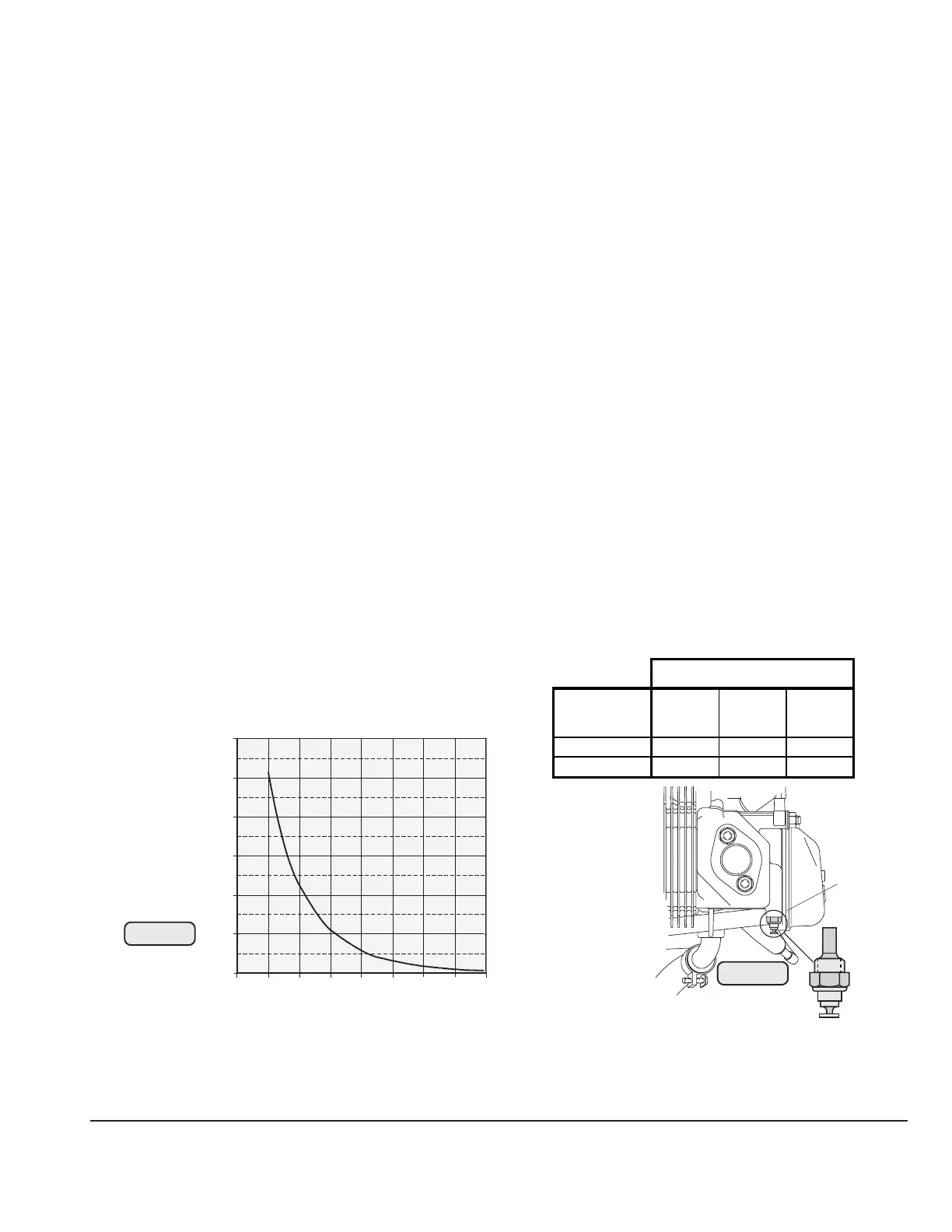
23.1) Sensor for cylinder head temperature
See Fig. 4, 89, and 90.
◆ NOTE: A direct reading of the coolant temperature is not provided for.
The temperature sensor (1) is directly fitted into cylinder head i.e. a direct temperature
reading of the cylinder head material is taken. This allows the exact measuring of the
cylinder head temperature even in the case of coolant loss.
◆ NOTE: Readings are taken on the hottest cylinder, depending on engine
installation.
- location: in the cylinder head of the cylinders 2 and 3, see Fig. 4.
- connection: spade terminal 6,3x0,8 to DIN 46247
- grounding: via engine block
- graph of sensor resistance over temperature
Fig. 89
Fig. 90
00327
12010080604020 140 160
1200
1000
(
Ω)
(°C)
800
600
400
200
0
■ CAUTION: The graph resistance over temperature has been determined, and is
effective at the following conditions only.
ambient temperature: 20 °C (68 °F)
tolerance: ± 10%
00227
04868
Axes
cylinder head
x axis
mm
y axis
mm
z axis
mm
2 -200,0 241,0 -157,0
3 -387,0 -241,0 -157,0
1

 Loading...


