page 134
July 01/2008
Effectivity: 914 Series
Edition 2 / Rev. 0
d04283
INSTALLATION MANUAL
BRP-Rotax
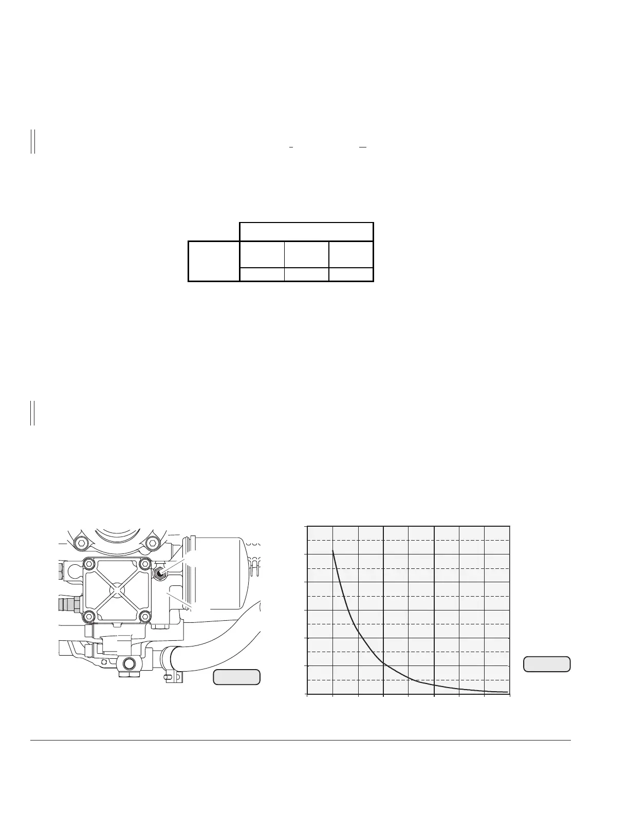
23.2) Sensor for oil temperature
See Fig. 91/92
- location: oil pump housing
- marking (2): marked with "TO" (temperature oil) on oil pump flange
■ CAUTION: To avoid any mix-up with indication wiring, mark this particular cable
also with "TO".
- position of the temperature sensor (1) on the oil pump flange:
Fig. 91
TO
Fig. 92
12010080604020 140 160
1200
1000
(
Ω)
(°C)
800
600
400
200
0
- connection of sensor wiring: spade terminal 6,3 x 0,8 to DIN 46247
- grounding: via engine block
- graph of sensor resistance over temperature
■ CAUTION: The graph resistance over temperature has been determined, and is
effective at the following conditions only.
ambient temperature: 20 °C (68 °F)
tolerance: ± 15%
BRP-Rotax offers a non-certified temperature indicating instrument. Refer to Illustrated
Parts Catalog, latest issue.
▲ WARNING: Certification to the latest requirements such as FAR of EASA has to be
conducted by the aircraft manufacturer.
00226
00227
04869
Axes
x axis
mm
y axis
mm
z axis
mm
-115 46 -150
point of
support
1
2

 Loading...


