ROXELL - 031 - 0516
FLEX-AUGER - INSTALLATION INSTRUCTIONS
III-14
BIN LOCATION
Check diagrams on pages III-15 - III-22. to determine the m ost suitable location for your bin.
Important are :
- height of horizontal tubes
- position of the first outlet
Note : when you install the boot under an angle of 30 the capacity of the Flex-Auger is reduced with a percent-
age up to 20 % according to the feed used.
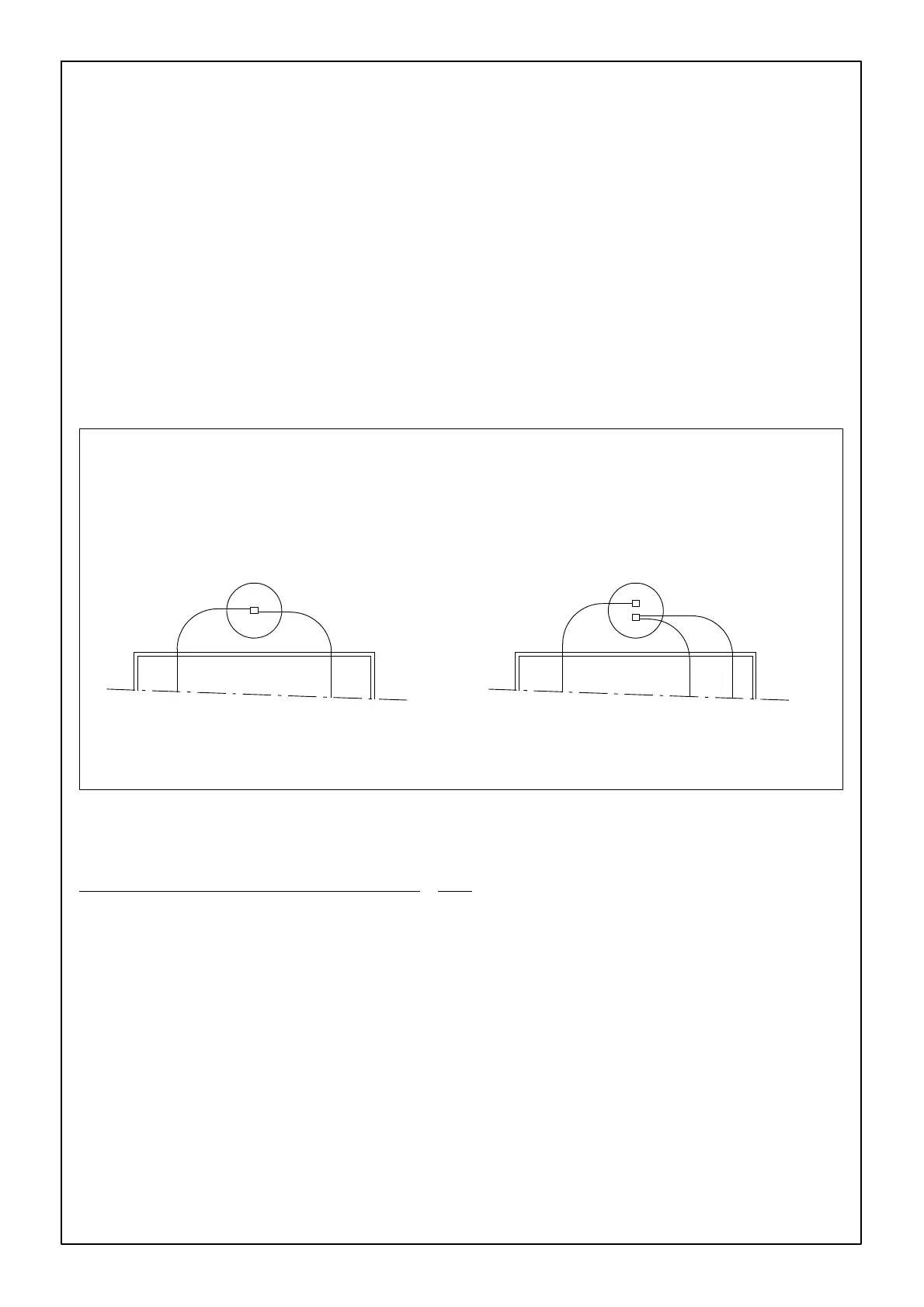
FIGURE 12. FIGURE 13.
By using a double intake boot (only for models
55, 75 and 90), you can start with a transport
system at either side.
If possible, install the bin in line with the Flex-Aug-
er
. Roxell provides 2 elbows 45 for a standard
system.
ELBOW DIAGRAMS
EXAMPLE PAGE III-15 : FLEX AUGER MODEL 55 - 0_ .
You want to enter the house under 30_ at a height of 2,2m.
Draw an auxiliary line A from height 2,2m to the point of intersection with the 30_ axis.
Drop the vertical B from this point of intersection.
On the diagram you see that the bin centre must be located at 4.40m from the house wall.
You want the bin centre at a certain distance from the wall and a certain angle of inclination.
Opposite procedure with adapted distances.