ROXELL - 031 - 0516
FLEX-AUGER - INSTALLATION INSTRUCTIONS
III-26
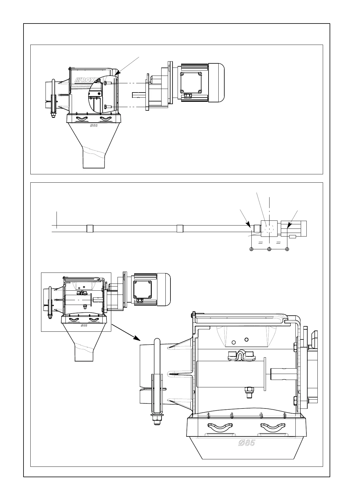
FIGURE 35.
Fix the power unit - on the opposite side of the tube anchor - to the con-
trol unit (with reinforcement plate) with the 4 bolts M8X20 supplied.
Fix the metal reinforcement plate at the inside.
CONTROL UNIT ASSEMBLY AND INSTALLATION
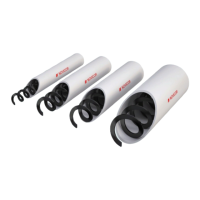
FIGURE 36.
Control unit.
Use chain and S-hooks at both suspension points :
- 1 before the control unit (A).
- 1 at the power unit (B).
SLIDE THE AUGER ANCHOR OVER THE GEAR-
HEAD SHAFT. TIGHTEN THE SCREWS, BUT
LEAVE THE ANCHOR BLOCK LOOSE TO INSTALL
THE AUGER.
A
B
Suspend the control unit at the proper location, in line with the tubes, so that the drop tube D. 85mm comes
in the center of the line.
B