ROXELL - 031 - 0516
FLEX-AUGER - INSTALLATION INSTRUCTIONS
III-23
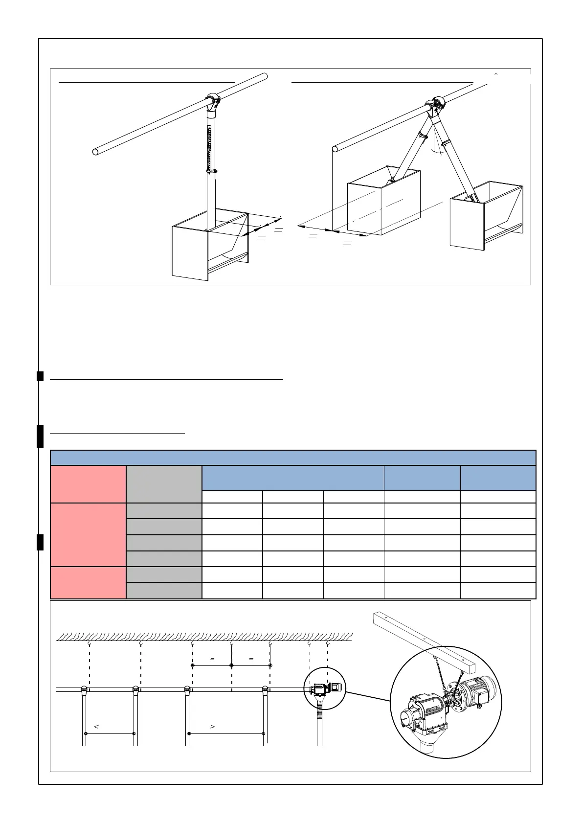
TRANSPORT LINE LOCATION
SINGLE ROW OF FEEDING TROUGHS
- in a feeding trough : against the
back wall.
- in 100kg hopper : in the center.
Install the drop tube.
FIGURE 26.
Suspend the line in the cen-
ter.
DOUBLE ROW OF FEEDING TROUGHS
Max. 45º
pellets
Max. 30º meal
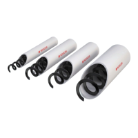
DISTANCE BETWEEN SUSPENSION POINTS
Recommendation: SUSPEND ALL Flex-Auger components !
Suspension in auger direction (no fixation of tube support).
Maximum tensile force of the S-hook : 60kg.
Closing the S-hook increases the resistance.
MODEL
55, 75, 90 AND 125 (NOVICOR/DENSICOR)
If distance between outlets is less than 2m , use one suspension per outlet.
Fordistancemorethan2m:useanextrasuspensioninbetween.
For tubes without outlets: suspension every 2m.
MODEL 90
AND 125 (METAL)
One suspension per 3M.
Maxload(kg) (inclusivesafetyfactor3)
Material Tube Flex Auger
Flex-Auger length
Extension
boot
Power unit
1m 2m 3m
NOVICOR/
DENSICOR
FA55 6 13 53 59
FA75 14 28 68 74
FA90 16 33 87 93
FA125 29 59 98 94
METAL
FA90 67 87 93
FA125 118 98 94
FIGURE 27.
2m 2m
FIGURE 28.