ROXELL - 031 - 0516
FLEX-AUGER - INSTALLATION INSTRUCTIONS
III-46
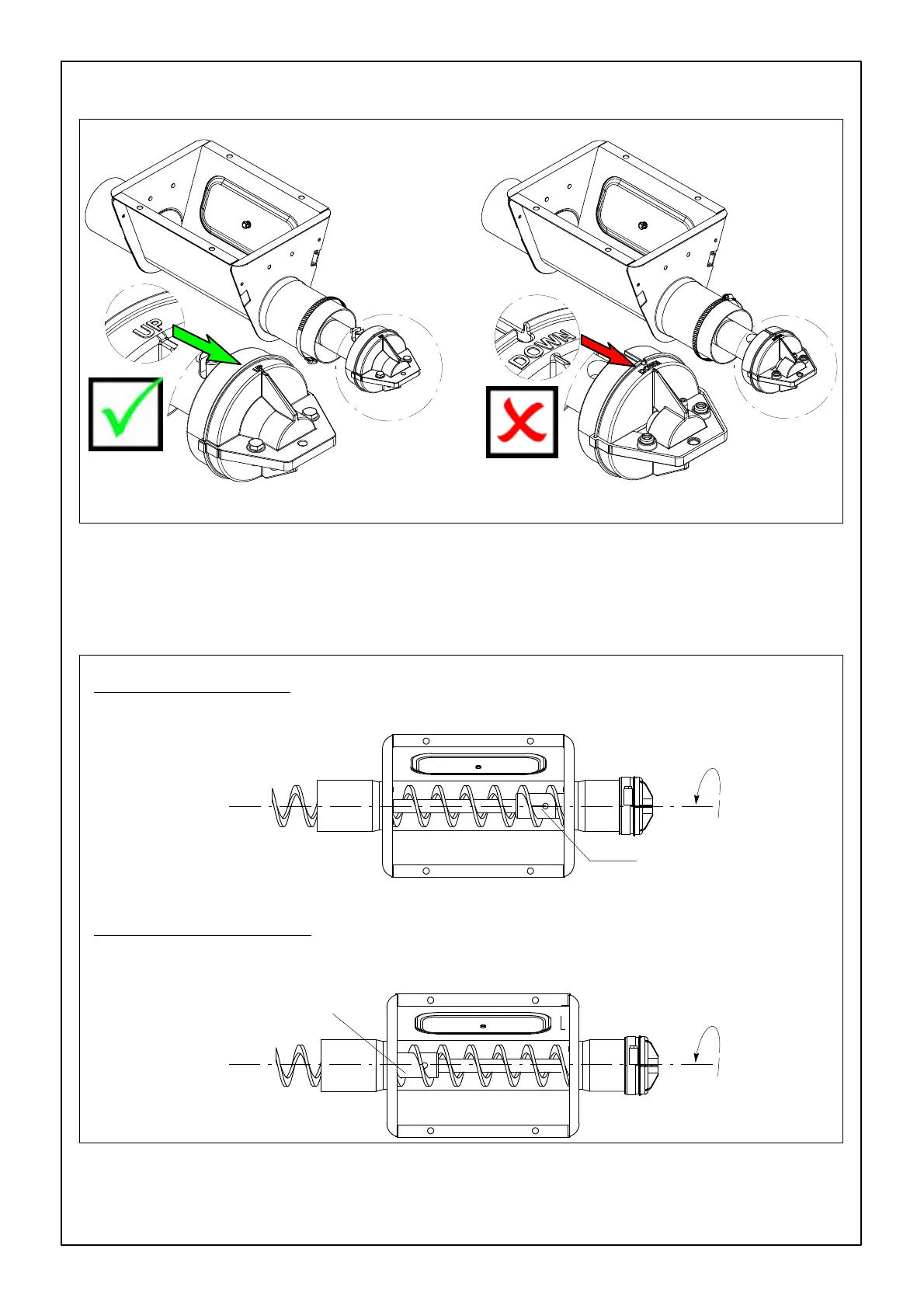
FIGURE 98.
BEARING CAP HOLDER
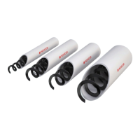
Minimum feed flow.
FLOW REGULATOR
OPEN
Flow regulator
Maximum feed flow.
FLOW REGULATOR CLOSED
FIGURE 99.
Flow regulator
FLOW REGULATION MODEL 75 & 90
CHECK IF THE DIRECTION OF ROTATION OF T HE AUGER IS COUNTER CLOCKWISE LOOKING
FROM BIN TO CONTROL UNIT.
IF YOU USE AN EXTENSION BOOT : Adjust flow regulator in such a way that the second part of the line could con-
vey more feed than the first part.