ROXELL - 031 - 0516
FLEX-AUGER - INSTALLATION INSTRUCTIONS
III-18
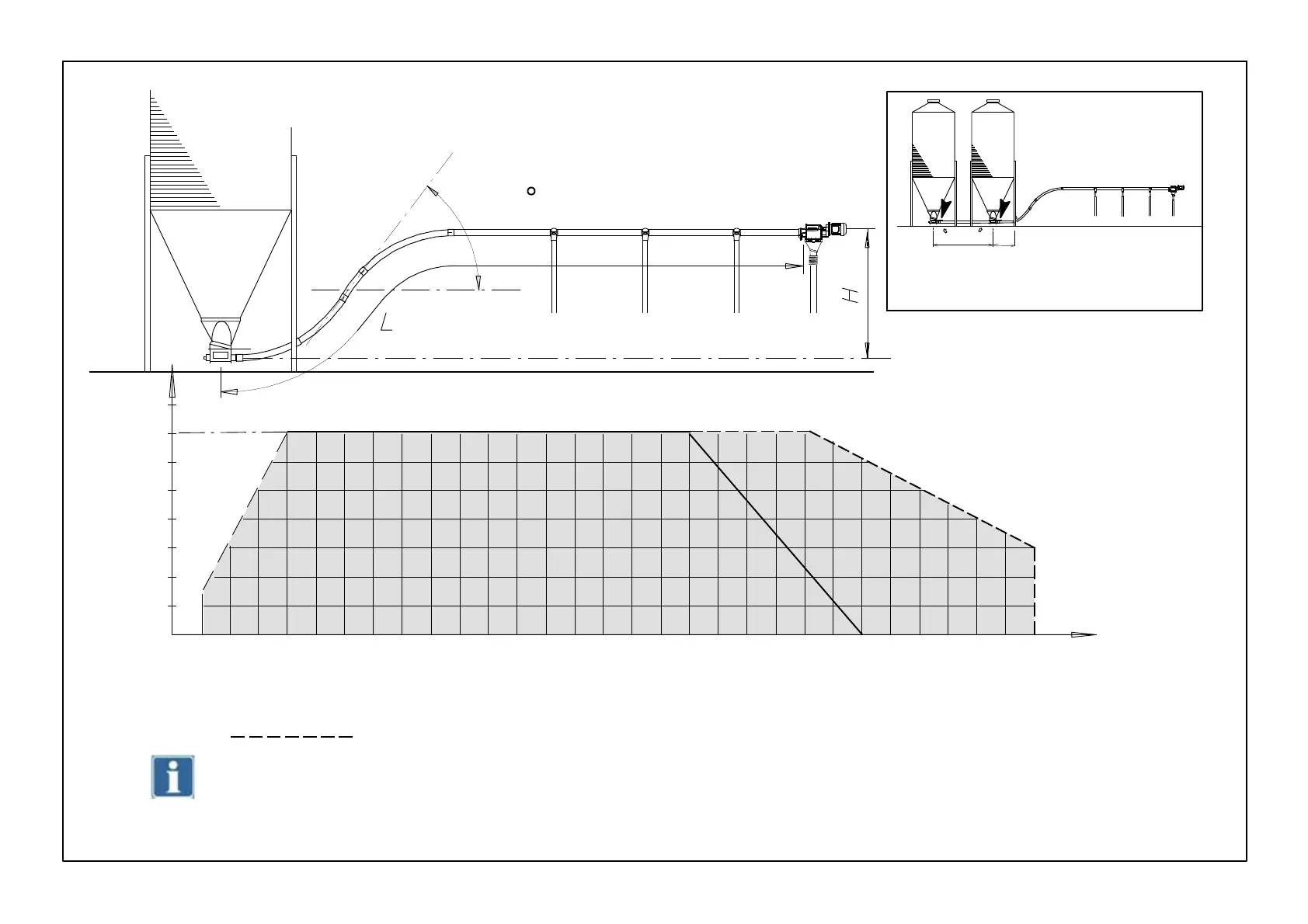
Thefirstextraelbow(45) reduces the maximum length with 3 meters. The followiing extra elbows with 4,5 m.
MAX. 75
FIGURE 20.
A b
Max. 3m.
Min.1,5m
0
3 6 9 121518212427303336394245485154576063666972757881848790
1
2
3
4
5
6
(m)
7
H
L(m)
with fill points every 0,5 m
All lengths within the graph are allowed. If dimentions pass the graph limits, use an extention boot, and consider the system as two separ-
ate Flex-Augers Model 55
GRAPH WITH MAXIMUM LENGTHS - MODEL 55