204
Using the Configurator
4. Press switch number 1 on node 3 to answer the call from node 2.
Node 2 and node 3 turn off their buzzers and the green LEDs turn solid.
The operators at all 3 nodes can now talk to each other.
5. Press switch number 0 on node 3 to disconnect the call from node 1.
6. Press switch number 1 on node 3 to disconnect the call from node 2.
19.44.3 Call Control
The operator can call all the nodes that are correlated to the node’s telephone/page selector
by pressing the Call Control switch on the master telephone (QMT-5302N(V)).
In this example three-node system, the following correlations have been made:
• Node 1 switch number 0 <--> Node 3 switch number 0
• Node 1 switch number 1 <--> Node 2 switch number 0
1. Press the Call Control switch on node 1.
Nodes 1, 2, and 3 sound their buzzers and the green LEDs blink.
2. Press switch number 0 on node 3 to answer the call from node 1.
All nodes turn off their buzzers.
The green LEDs on node 1 and node 3 turn solid.
The green LED on node 2 blinks (the call from node 1 can still be answered).
3. Press switch number 0 on node 3 to disconnect the call from node 1.
4. Press the Deselect All switch on node 1 to disconnect all calls from this node.
19.44.4 Master telephones in the Configurator
This section describes how to set up master telephones on the three-node system described
in section 19.44.2 on page 203.
Add the audio controllers and master telephones
Add an audio controller, a master telephone, and a telephone/page selector to each node as
described in sections 19.43.1, 19.43.3 and 19.43.4.
Assign the phone selector switches
1. Select the Telephone/Page Selector under node 1’s Main Display.
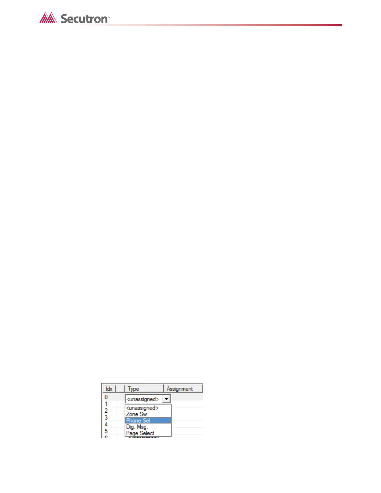
2. For switch number 0, double-click <unassigned> and select Phone Sel.
Figure 148 Make a Switch a Phone Selector Switch
 Loading...


