194
Using the Configurator
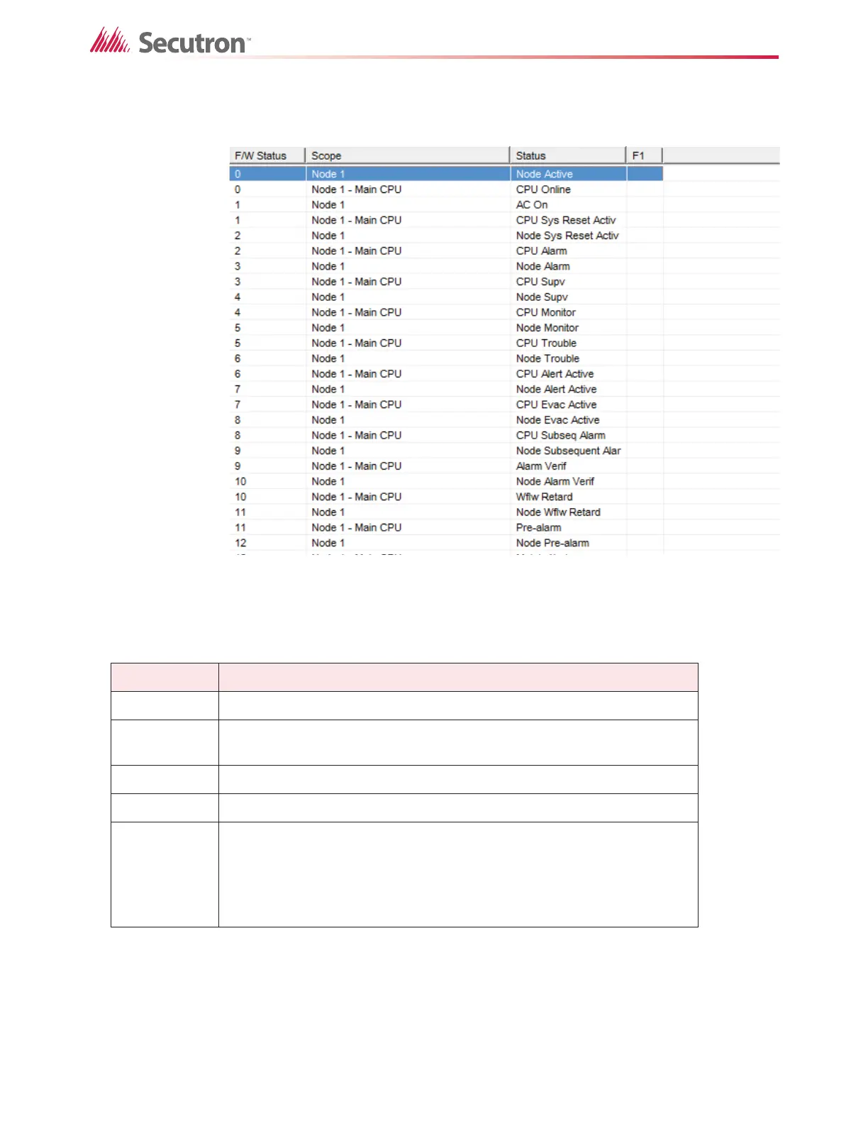
The Scope column specifies the Node and CPU of the status. You must have defined a
suitable LED to accept the correlation from the Node or Node/CPU specific status.
Figure 145 System Status
Table 23 describes the columns in the System Status view.
Some System Statuses can also be correlated to switches. Examples are Signal Silence,
Fire Drill, Aux Disc, Total Evacuation. When one of these items is selected, the Correlations
Pane shows any display adder switches that are correlated to the item. This does not include
remote switches (input circuits or devices of type Input Module that are assigned to a
Common System Status).
Table 23 System Status
Name Description
F/W Status The firmware status number.
Scope
Either Common for system wide statuses or the Node name, or Node CPU
combination of the status.
Status A short description of the status.
F1 Flag field: NS for Non-Silenceable or blank.
F2
On a two stage system, select GA if you want the outputs correlated to a
Common System Status to sound at the Evac rate. If this column is blank,
the outputs sound at the Alert rate.
You can specify the tones for Evac and Alert in the Audio Setup window.
See chapter 16.
 Loading...


