Kingfisher Plus+ Hardware Manual
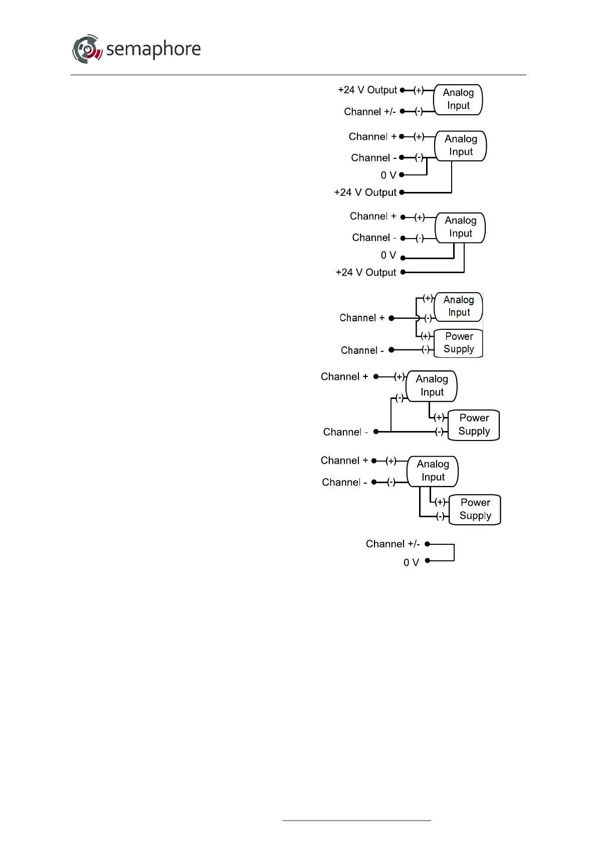
2 wire transmitter
(powered by module)
3 wire transmitter
(powered by module)
4 wire transmitter
(powered by module)
2 wire transmitter
(powered externally)
3 wire transmitter
(powered externally)
4 wire transmitter
(powered externally)
Loop
* When using the +24 V output to power a transducer, the negative input terminal of the analogue input
channel (2, 4, 6, 8, 12, 14, 16 or 18) must be wired to the 0 V terminal (10 or 20). This will complete the
current loop due to electrical isolation between the input channel and the module +24 V Output.
Note: Any channels sharing the same power source (e.g. +24 V from module or a field power supply)
are no longer isolated from one other.
Hardware Manual Version 7.16
http://www.servelec-semaphore.com/
Page 143