Kingfisher Plus+ Hardware Manual
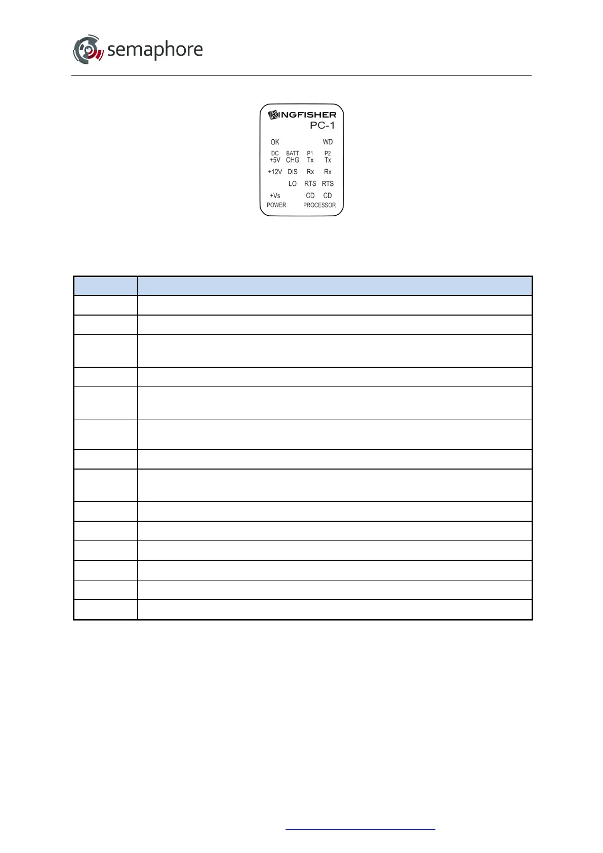
4.2.3 PC-1 Module LEDs
PC-1
Both of the communications ports have Tx, Rx, RTS and CD LEDs in a vertical group as
shown above.
PC-1 LED Description
OK
ON when module is functioning OK
DC +5V
ON when the internal 5 V supply is OK. This LED should always be on
+12V
ON when the internal 12 V supply is OK. This LED should always be on (software
controlled)
T1
Test LED 1. Flashes during Power Down mode.
+Vs
ON when the Auxiliary 24 V supply is OK (will only display if the 24 V converter is
installed).
BATT
CHG*
ON when the battery is being charged
DIS*
ON when the battery is being discharged
LO
ON when the battery voltage is low (For a PC-1 this occurs when the supply voltage is
less than about 11.2 V
DC
)
T2
Test LED 2. Not currently used.
Tx
ON when port is transmitting
Rx
ON when port is receiving
RTS
Request to send. Set ON to begin transmitting
CD
Carrier detect: ON while a communications signal is detected.
WD
Processor Watchdog Timer. Set ON when the processor is reset.
* The battery charging (BATT CHG) and battery discharging (DIS) LEDs will sometimes
flicker on and off when the battery is charged to the optimum level or if no battery is
connected.
Hardware Manual Version 7.16
http://www.servelec-semaphore.com/
Page 64