Kingfisher Plus+ Hardware Manual
Digital Inputs are connected to the input optocouplers via series diodes, resistors and
3.6 mA current limiters. Optocouplers with integrated Schmitt triggers are installed on first
four (high-speed) channels. When input voltage and, consequently, input current of an
optocoupler exceeds its threshold, microcontroller (MCU) reads this input as ‘1’, otherwise it
is ‘0’.
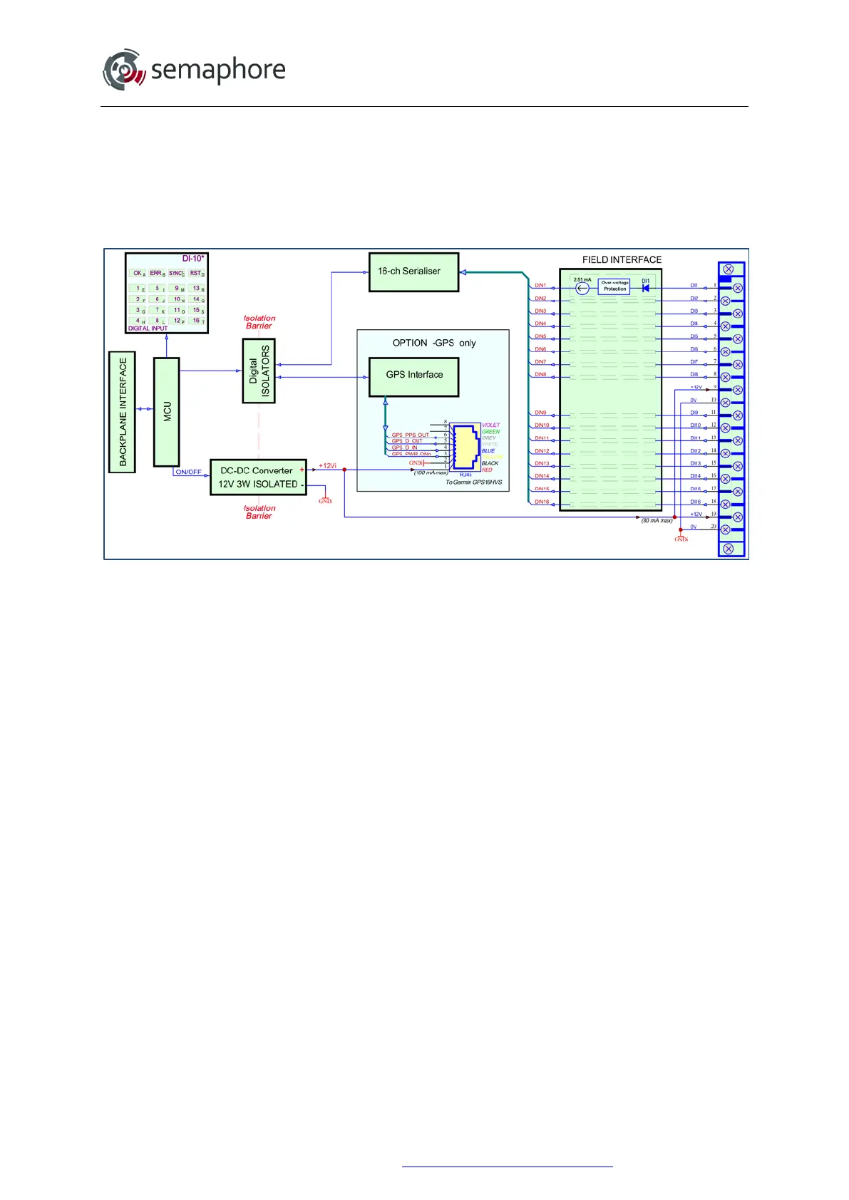
Block-diagram of DI-10 v4.3 module is shown on the picture below.
DI-10 v4.3 Block Diagram
Digital Inputs are connected to a digital serialiser via series diodes and over-voltage
protection circuits. The digital serialiser has its threshold input current set (and limited) to
2.51 mA. External signal sources should be able to supply 2.51 mA current to the DI-10 v4.3
module. When the input voltage exceeds its threshold, the microcontroller (MCU) reads this
input as ‘1’, otherwise it is ‘0’.
11.3.4 Configurable Functions
The first 4 channels of the DI-10 v3.2 and all channels of the DI-10 v4.3 are high speed and
capable of counting up to 10kHz, while channels 5 to 16 of the DI-10 v3.2 can count up to
1 kHz.
Seven user-configurable counters are available which appear as 16-bit unsigned integer
values in the analogue input register. Each of these counters can be configured either to
measure frequency, to count pulses or to decode quadrature signals. Any channel from 1 to
16 can be assigned as an input to any frequency or pulse counter. Any pair of eight channel
pairs (1-2, 3-4, etc.) can be assigned as inputs to any quadrature counter.
Channel inversion can be configured on any input channel. Normally a high voltage level
results in a logical HIGH state (1) to be set in the digital input register with the corresponding
LED illuminating on the front panel. By enabling channel inversion, a low voltage level
applied to an input will result in a logical HIGH (1).
Software debounce can be activated on any input channel. The time constant can be
configured from 1 ms to 250 ms. When AC inputs are used, the input channel must be
configured with the debounce filter set to ‘AC Filter’ as shown below.
Hardware Manual Version 7.16
http://www.servelec-semaphore.com/
Page 158