Kingfisher Plus+ Hardware Manual
Digital IO
Input characteristics are compatible with a wide range of user supplied input devices, such
as push buttons, limit switches and electronic proximity switches, whilst outputs can control a
wide range of user supplied load devices such as: motor starters, solenoids and indicators.
Power for the internal relay circuits is provided by the +12 V
DC
bus on the backplane. The
user must supply the AC or DC power to operate field devices. An internal fuse protects the
relay contacts should ratings be exceeded.
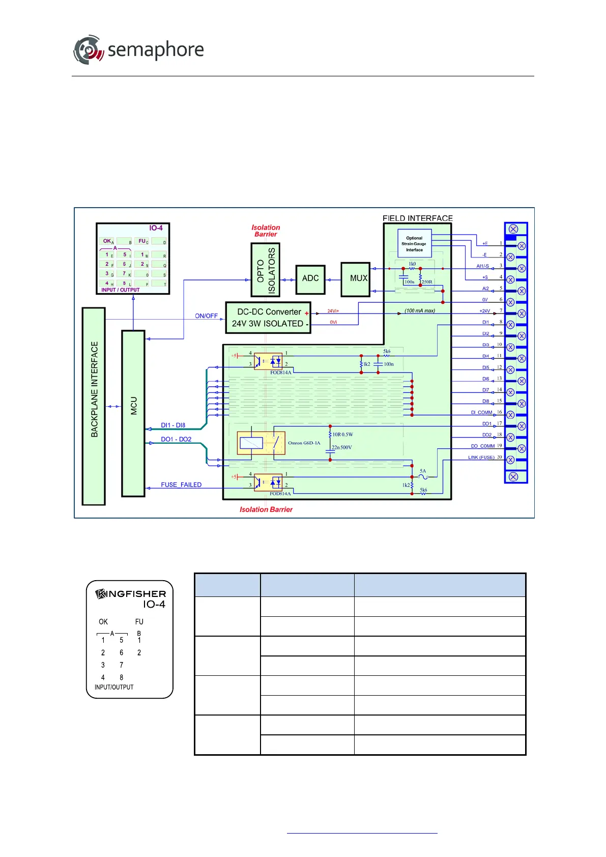
Block-diagram of the IO-4 module is shown on the figure below.
IO-4 Block Diagram
14.3.2 IO-4 Module LEDs
LED State Description
OK
OFF Module fault (no power)
ON Normal
FU
OFF Fuse OK
ON Fuse fail
A1-A8
OFF Digital input OFF
ON Digital input ON
B1-B2
OFF Digital output OFF (open)
ON Digital output ON (closed)
Hardware Manual Version 7.16
http://www.servelec-semaphore.com/
Page 212